CHAPTER 5: SETTINGS CONTROL ELEMENTS
C70 CAPACITOR BANK PROTECTION AND CONTROL SYSTEM – INSTRUCTION MANUAL 5-273
5
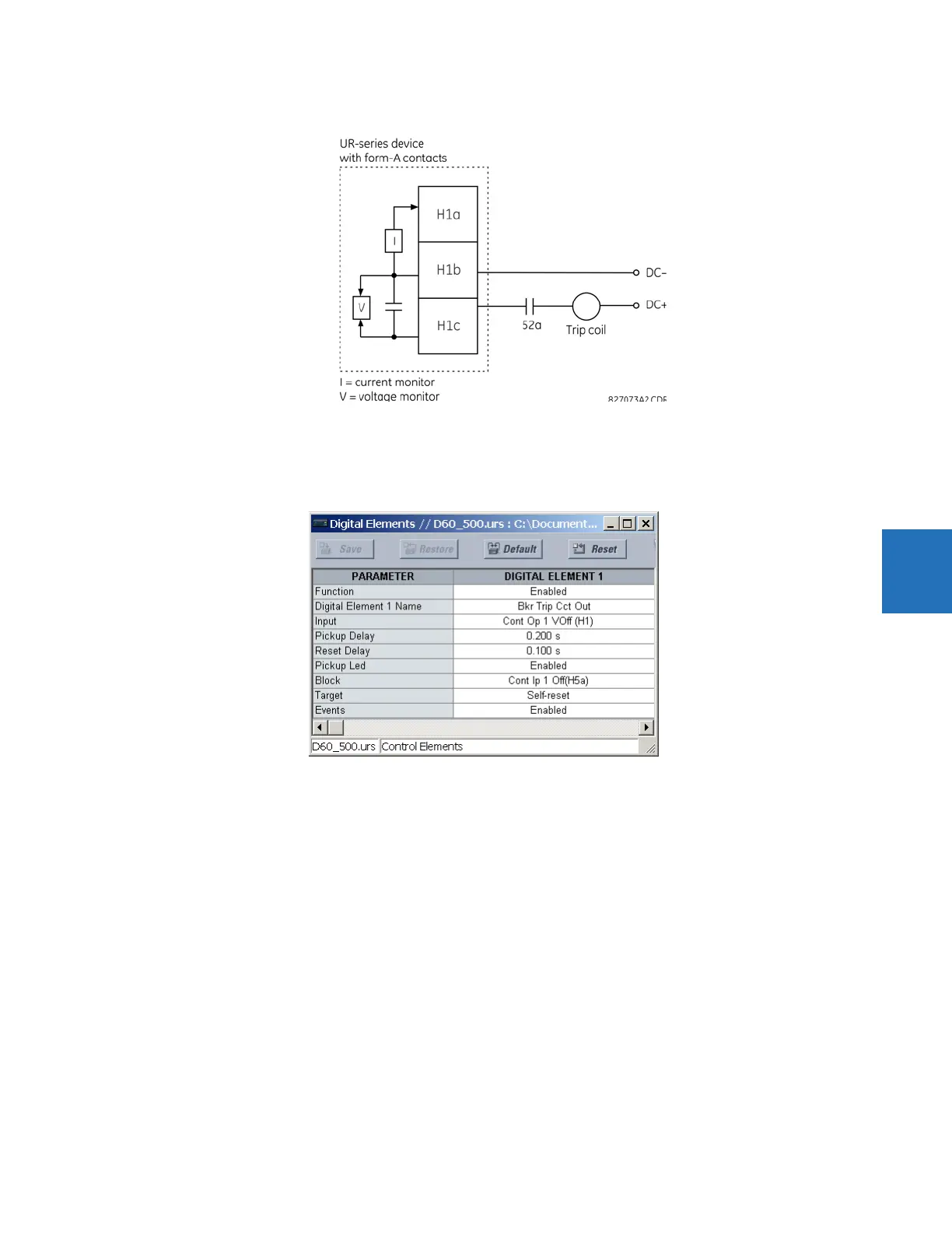
Figure 5-149: Trip circuit example 1
Assume the output contact H1 is a trip contact. Using the contact output settings, this output is given an ID name; for
example, “Cont Op 1." Assume a 52a breaker auxiliary contact is connected to contact input H7a to monitor breaker status.
Using the contact input settings, this input is given an ID name, for example, “Cont Ip 1," and is set “On” when the breaker is
closed. The settings to use digital element 1 to monitor the breaker trip circuit are indicated (EnerVista example shown).