CHAPTER 5: SETTINGS CONTROL ELEMENTS
C70 CAPACITOR BANK PROTECTION AND CONTROL SYSTEM – INSTRUCTION MANUAL 5-287
5
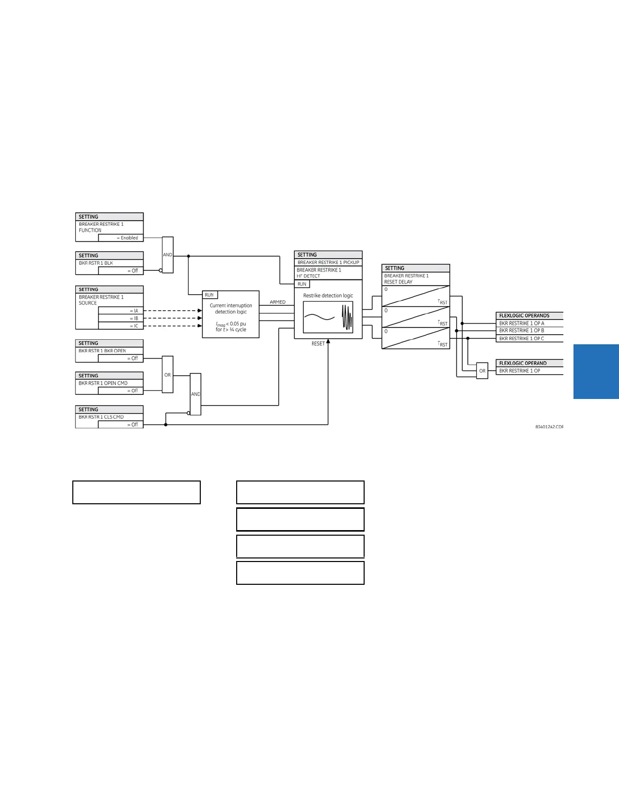
BREAKER RESTRIKE 1 HF DETECT — Enables/disables high-frequency (HF) pattern detection when breaker restrike occurs.
High-frequency pattern is typical for capacitor bank, cables, and long transmission lines applications.
BRK RSTR 1 BRK OPEN — Assigns a FlexLogic operand indicating the open position of the breaker. It must be logic “1” when
the breaker is open. It is important to assign either 52 contact with this setting or breaker close command with
BRK RSTR 1
CLS CMD
setting to give clear indication to the relay about breaker status.
BRK RSTR 1 OPEN CMD — Assigns a FlexLogic operand indicating a breaker open command. It must be logic “1” when the
breaker is opened, either manually or from protection logic.
BRK RSTR 1 CLS CMD — Assigns a FlexLogic operand indicating a breaker close command. It must be logic “1” when the
breaker is closed.
Figure 5-157: Breaker restrike logic
5.8.10.5 VT fuse failure
SETTINGS CONTROL ELEMENTS MONITORING ELEMENTS VT FUSE FAILURE 1(6)
Every signal source includes a fuse failure scheme.
The VT fuse failure detector is used to raise an alarm and/or block elements that operate incorrectly for a full or partial loss
of AC potential caused by one or more blown fuses. Some elements that can be blocked (via the BLOCK input) are distance,
voltage restrained overcurrent, and directional current.
There are two classes of fuse failure that occur:
• Class A — Loss of one or two phases
• Class B — Loss of all three phases
Different means of detection are required for each class. An indication of class A failures is a significant level of negative-
sequence voltage, whereas an indication of class B failures is when positive sequence current is present and there is an
insignificant amount of positive sequence voltage. Also, a rapid decrease in the phase voltages magnitude from a healthy
VT FUSE FAILURE 1
VT FUSE FAILURE 1
FUNCTION: Disabled
Range: Disabled, Enabled
VT FUSE FAILURE 1
ALARM DELAY: 1.000 s
Range: 0.000 to 65.535 s in steps of 0.001
NEUTRAL WIRE OPEN 1
DETECTION: Disabled
Range: Disabled, Enabled
NEUTRAL WIRE OPEN 1
3 HARM PKP: 0.100 pu
Range: 0.004 to 3.000 pu in steps of 0.001