CHAPTER 5: SETTINGS CONTROL ELEMENTS
C70 CAPACITOR BANK PROTECTION AND CONTROL SYSTEM – INSTRUCTION MANUAL 5-291
5
When current is less than the dropout level, I
n
> 0.97 × k × I
B
, the element starts decreasing the thermal energy:
Eq. 5-27
where
∆t is the power cycle duration
n is the power cycle index
t
op(In)
is the trip time calculated at index n as per the IEC255-8 cold curve or hot curve equations
t
rst(In)
is the reset time calculated at index n as per the reset time equation
I
n
is the measured overload RMS current at index n
E
n
is the accumulated energy at index n
E
n–1
is the accumulated energy at index n – 1
The thermal overload protection element removes the
THERMAL PROT 1 OP output operand when E < 0.05. In case of
emergency, the thermal memory and
THERMAL PROT 1 OP output operand can be reset using THERM PROT 1 RESET setting.
All calculations are performed per phase. If the accumulated energy reaches value 1 in any phase, the thermal overload
protection element operates and only resets when energy is less than 0.05 in all three phases.
Table 5-38: Typical time constants
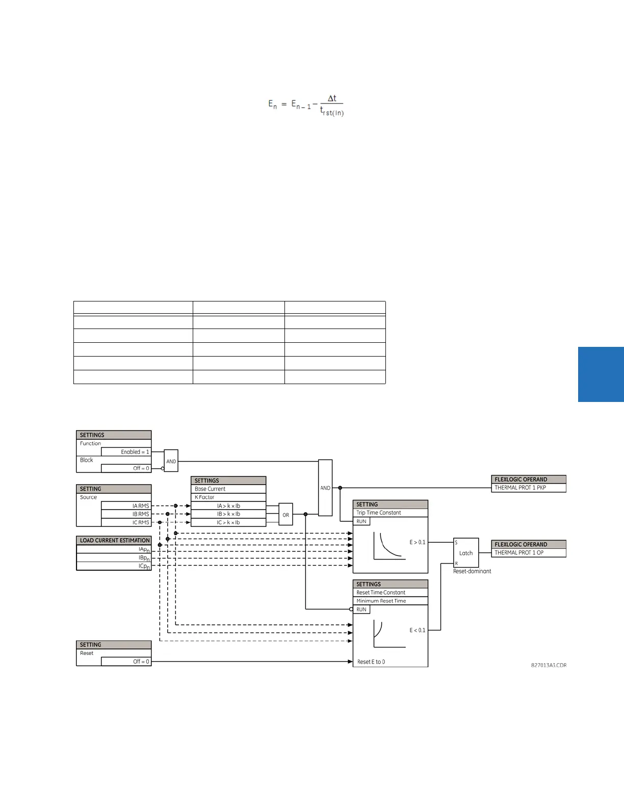
The figure shows the logic for the thermal overload protection element.
Figure 5-160: Thermal overload protection logic
Protected equipment Time constant Minimum reset time
Capacitor bank 10 minutes 30 minutes
Overhead line 10 minutes 20 minutes
Air-core reactor 40 minutes 30 minutes
Busbar 60 minutes 20 minutes
Underground cable 20 to 60 minutes 60 minutes