CHAPTER 5: SETTINGS INPUTS/OUTPUTS
C70 CAPACITOR BANK PROTECTION AND CONTROL SYSTEM – INSTRUCTION MANUAL 5-297
5
Program the Latching Outputs by making the following changes in the SETTINGS INPUTS/OUTPUTS CONTACT
OUTPUTS CONTACT OUTPUT H1a
menu (assuming an H4L module):
OUTPUT H1a OPERATE: “PUSHBUTTON 1 ON”
OUTPUT H1a RESET: “PUSHBUTTON 2 ON”
Program the pushbuttons by making the following changes in the PRODUCT SETUP USER-PROGRAMMABLE PUSHBUTTONS
USER PUSHBUTTON 1
and USER PUSHBUTTON 2 menus:
PUSHBUTTON 1 FUNCTION: “Self-reset”
PUSHBTN 1 DROP-OUT TIME: “0.00 s”
PUSHBUTTON 2 FUNCTION: “Self-reset”
PUSHBTN 2 DROP-OUT TIME: “0.00 s”
Application example 2
A relay, having two latching contacts H1a and H1c, is to be programmed. The H1a contact is to be a Type-a contact, while
the H1c contact is to be a Type-b contact (Type-a means closed after exercising the operate input; Type-b means closed
after exercising the reset input). The relay is to be controlled from virtual outputs: VO1 to operate and VO2 to reset.
Program the Latching Outputs by making the following changes in the
SETTINGS INPUTS/OUTPUTS CONTACT
OUTPUTS CONTACT OUTPUT H1a
and CONTACT OUTPUT H1c menus (assuming an H4L module):
OUTPUT H1a OPERATE: “VO1”
OUTPUT H1a RESET: “VO2”
OUTPUT H1c OPERATE: “VO2”
OUTPUT H1c RESET: “VO1”
Since the two physical contacts in this example are mechanically separated and have individual control inputs, they do not
operate at exactly the same time. A discrepancy in the range of a fraction of a maximum operating time can occur.
Therefore, a pair of contacts programmed to be a multi-contact relay do not guarantee any specific sequence of operation
(such as make before break). If required, the sequence of operation must be programmed explicitly by delaying some of the
control inputs as shown in the next application example.
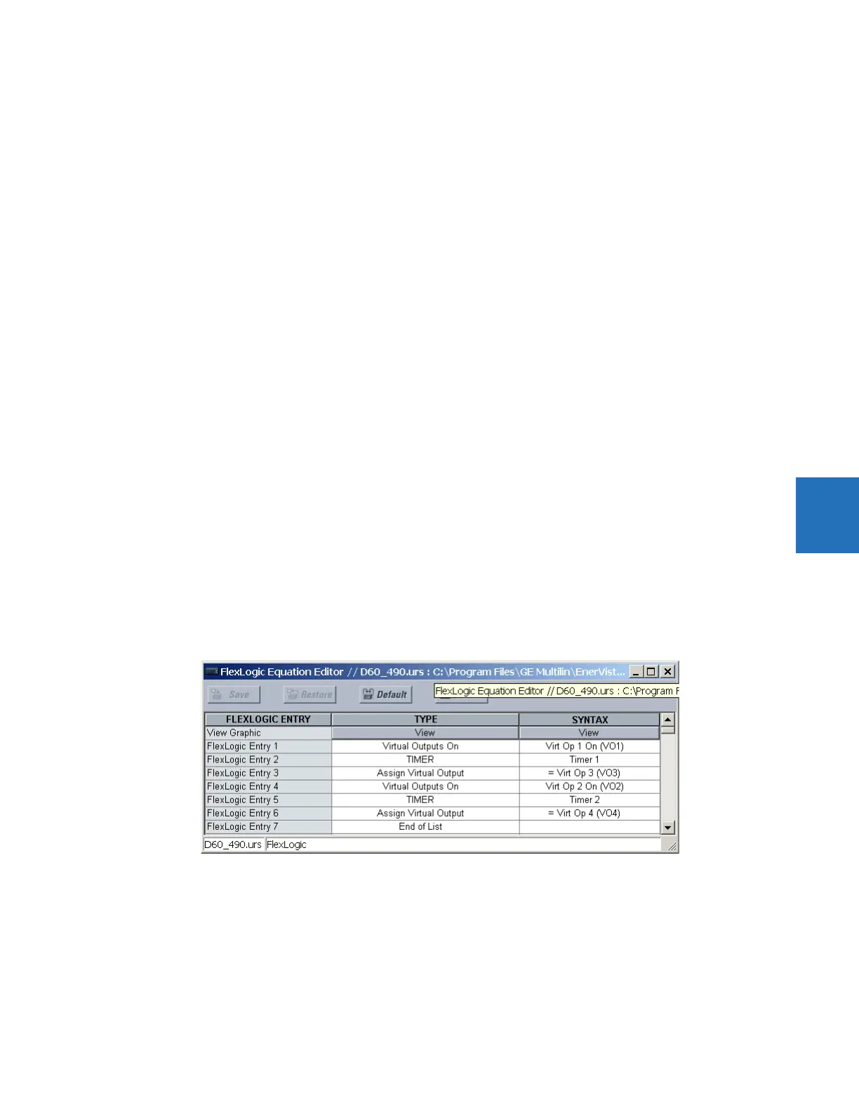
Application example 3
A make before break functionality must be added to the preceding example. An overlap of 20 ms is required to implement
this functionality.
Write the following FlexLogic equation (EnerVista example shown).
Set both timers (Timer 1 and Timer 2) to 20 ms pickup and 0 ms dropout.
Program the Latching Outputs by making the following changes in the
SETTINGS INPUTS/OUTPUTS CONTACT
OUTPUTS CONTACT OUTPUT H1a
and CONTACT OUTPUT H1c menus (assuming an H4L module):
OUTPUT H1a OPERATE: “VO1”
OUTPUT H1a RESET: “VO4”
OUTPUT H1c OPERATE: “VO2”
OUTPUT H1c RESET: “VO3”