5-302 C70 CAPACITOR BANK PROTECTION AND CONTROL SYSTEM – INSTRUCTION MANUAL
INPUTS/OUTPUTS CHAPTER 5: SETTINGS
5
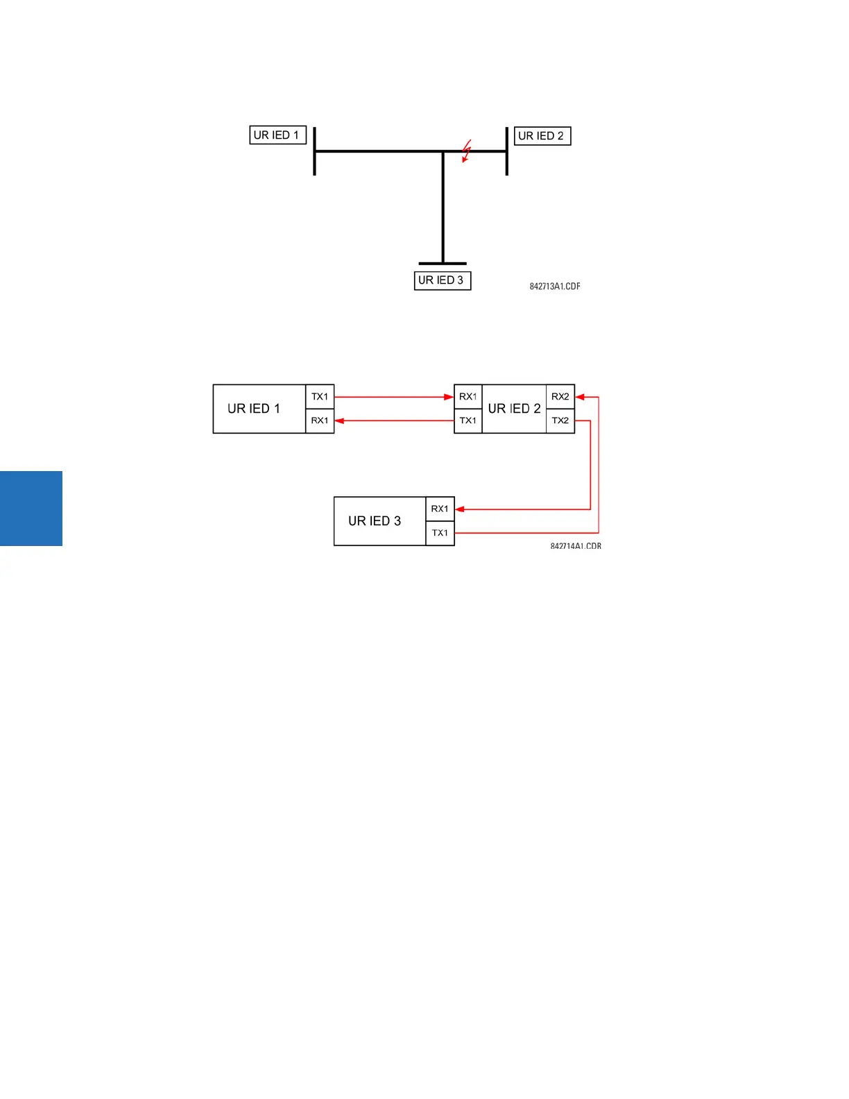
Figure 5-167: Three-terminal line application
Assume the Hybrid Permissive Overreaching Transfer Trip (Hybrid POTT) scheme is applied using the architecture shown as
follows. The scheme output operand
HYB POTT TX1 is used to key the permission.
Figure 5-168: Single-channel open-loop configuration
In this architecture, Devices 1 and 3 do not communicate directly. Therefore, Device 2 must act as a ‘bridge’. The following
settings are applied:
UR IEC 1:
DIRECT OUT 2 OPERAND: "HYB POTT TX1"
DIRECT INPUT 5 DEVICE ID: "2"
DIRECT INPUT 5 BIT NUMBER: "2" (this is a message from IED 2)
DIRECT INPUT 6 DEVICE ID: "2"
DIRECT INPUT 6 BIT NUMBER: "4" (effectively, this is a message from IED 3)
UR IED 3:
DIRECT OUT 2 OPERAND: "HYB POTT TX1"
DIRECT INPUT 5 DEVICE ID: "2"
DIRECT INPUT 5 BIT NUMBER: "2" (this is a message from IED 2)
DIRECT INPUT 6 DEVICE ID: "2"
DIRECT INPUT 6 BIT NUMBER: "3" (effectively, this is a message from IED 1)
UR IED 2:
DIRECT INPUT 5 DEVICE ID: "1"
DIRECT INPUT 5 BIT NUMBER: "2"
DIRECT INPUT 6 DEVICE ID: "3"
DIRECT INPUT 6 BIT NUMBER: "2"
DIRECT OUT 2 OPERAND: "HYB POTT TX1"
DIRECT OUT 3 OPERAND: "DIRECT INPUT 5" (forward a message from 1 to 3)
DIRECT OUT 4 OPERAND: "DIRECT INPUT 6" (forward a message from 3 to 1)
The figure shows the signal flow among the three IEDs.