CHAPTER 6: ACTUAL VALUES METERING
C70 CAPACITOR BANK PROTECTION AND CONTROL SYSTEM – INSTRUCTION MANUAL 6-15
6
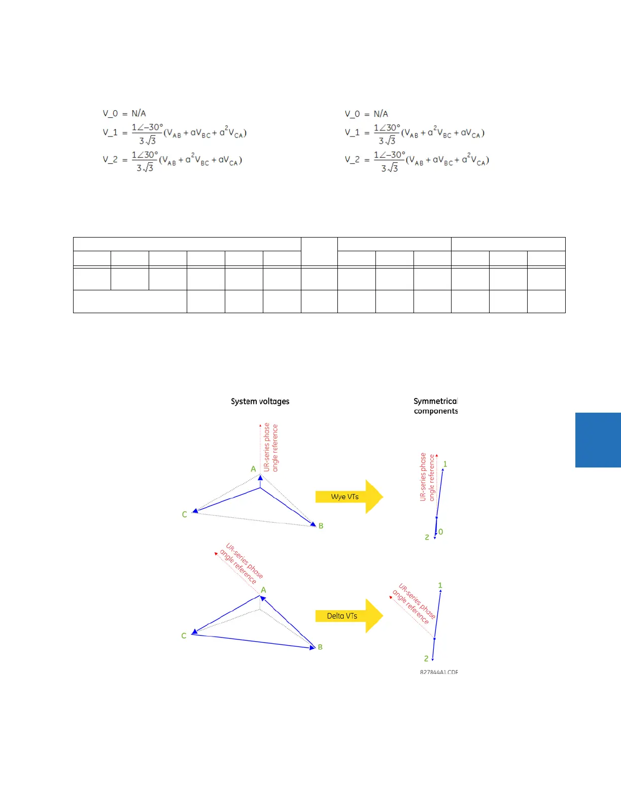
DELTA-connected instrument transformers
The zero-sequence voltage is not measurable under the Delta connection of instrument transformers and is defaulted to
zero. The table below shows an example of symmetrical components calculations for the ABC phase rotation.
Table 6-1: Symmetrical components calculation example
* The power system voltages are phase-referenced – for simplicity – to V
AG
and V
AB
, respectively. This, however, is a
relative matter. It is important to remember that the C70 displays are always referenced as specified under
SETTINGS
SYSTEM SETUP POWER SYSTEM FREQUENCY AND PHASE REFERENCE
.
The example above is illustrated in the following figure.
Figure 6-5: Measurement convention for symmetrical components
• ABC phase rotation: • ACB phase rotation:
SYSTEM VOLTAGES, sec. V * VT conn. relay INPUTS, sec. V SYMM. COMP, sec. V
V
AG
V
BG
V
CG
V
AB
V
BC
V
CA
F5ac F6ac F7ac V
0
V
1
V
2
13.9
∠0°
76.2
∠–125°
79.7
∠–250°
84.9
∠–313°
138.3
∠–97°
85.4
∠–241°
WYE 13.9
∠0°
76.2
∠–125°
79.7
∠–250°
19.5
∠–192°
56.5
∠–7°
23.3
∠–187°
UNKNOWN (only
V
1
and V
2
can be determined)
84.9
∠0°
138.3
∠–144°
85.4
∠–288°
DELTA 84.9
∠0°
138.3
∠–144°
85.4
∠–288°
N/A 56.5
∠–54°
23.3
∠–234°