9-10 C70 CAPACITOR BANK PROTECTION AND CONTROL SYSTEM – INSTRUCTION MANUAL
OVERVIEW CHAPTER 9: THEORY OF OPERATION
9
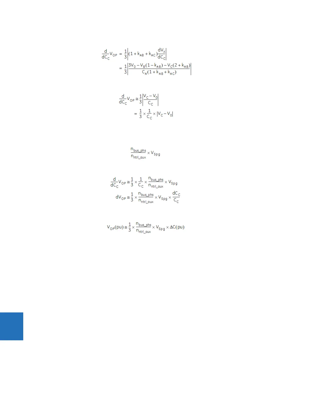
This can be substituted into equation 9.33 to obtain:
Eq. 9-37
For our purposes, C
A
≅ C
B
≅ C
C
, so k
AB
≅ 1 and k
AC
≅ 1. This results in:
Eq. 9-38
Under normal system conditions (non-fault), V
C
>> V
0
, and V
C
is the system phase-to-ground voltage. The system voltage
V
Spg
, which by convention is on the bus voltage base, converted to the base of nominal value of the neutral-point VT used
in these equations, is:
Eq. 9-39
This gives:
Eq. 9-40
This can be written as:
Eq. 9-41
In these equations, ΔC(pu) is the capacitance change as a per-unit of the leg capacitance, and V
OP
(pu) is the operating
signal resulting from the failure in per-unit of the nominal value of the neutral-point VT. V
Spg
is the system phase-to-ground
voltage in per-unit of the nominal system phase-to-ground voltage, so can be taken as 1 when the system is normal (not
faulted). Note however that under external fault conditions sensitivity can be much different from the non-fault sensitivity.
n
bus_phs
and n
ntrl_aux
are the VT ratios of the phase VT bank of the bus source and of the auxiliary VT channel of the neutral
source, respectively.
Note that under external fault conditions sensitivity can be much different form the non-fault sensitivity. To prevent mis-
operation, use a restraint and/or coordinating time delay.
9.1.4.4 Restraint
Severe system voltage unbalance, such as can occur during near-by bolted ground faults, can exacerbate measurement
error in V
X
or V
0
, resulting in spurious operating signal. In addition, as discussed, the sensitivity can be affected. To prevent
operation under these conditions, percent restraint supervision is provided using a restraint signal that is the magnitude of
the vector sum of V
X
and V
0
, defined as follows.
V
REST
= |V
X
+ V
0
| Eq. 9-42
During external ground faults, these two voltages are approximately in phase generating a large restraining signal being
twice the zero-sequence voltage at the bus. A slope of few percent is typically sufficient to provide good security under
large system unbalances.