9-18 C70 CAPACITOR BANK PROTECTION AND CONTROL SYSTEM – INSTRUCTION MANUAL
OVERVIEW CHAPTER 9: THEORY OF OPERATION
9
The final step assumes C
A1
≅ C
A2
and replaces the phase current vector with its magnitude. This can be written as:
Eq. 9-66
Alternately, we can say:
Eq. 9-67
where ΔC(pu) represents the capacitance change as a per-unit value of the string capacitance, and I
OP
(pu) represents the
operating signal resulting from the failure in per-unit of the nominal current of the differential source. I
A
represents the
phase A terminal current on the same base. When the system is normal (no fault), I
A
can be taken as the capacitor bank's
rated primary per-phase current I
rated
converted to the differential source base. For example, I
A
=I
rated
/I
base
, where I
base
is again the differential CT primary current rating, or with system normal:
Eq. 9-68
Note that under external fault conditions, sensitivity can be much different from the non-fault sensitivity.
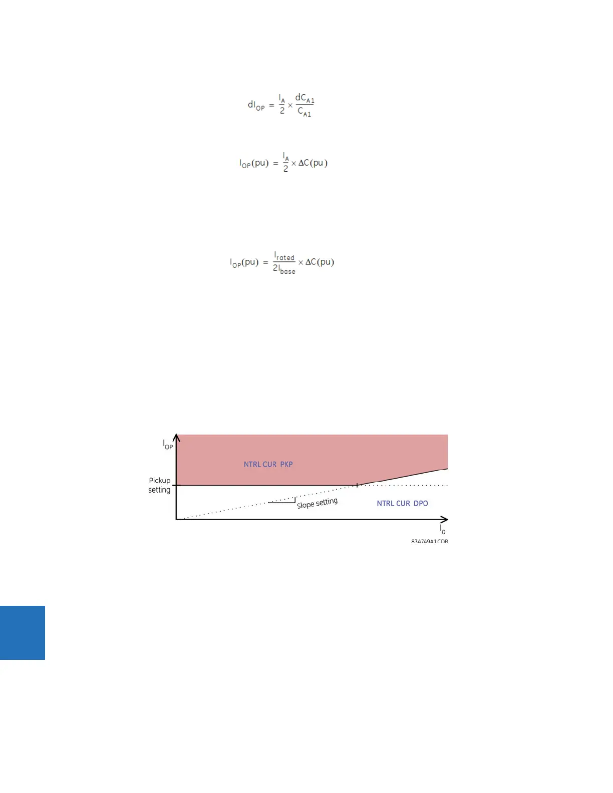
9.1.6.4 Restraint
Severe system voltage unbalance, such as can occur during near-by bolted ground faults, can exacerbate measurement
error, resulting in spurious operating signal. To prevent operation under these conditions, percent restraint supervision is
applied using a restraint signal that is the magnitude of the zero-sequence current.
Typically, a few percent of slope is enough to ensure security of the function. The factor compensating for the inherent
bank unbalance zeroes out the operating signal under relatively balanced bank currents. If the said currents contain a
significant zero sequence component, the quality of compensation is lower, hence the need for the restraint, and this slope
setting.
Figure 9-7: Neutral current unbalance restraint
9.1.6.5 Auto-setting
As a convenient alternative to manually determining the unbalance k-factor settings, the relay can automatically calculate
these settings from its own measurements while the capacitor is in-service, as described in the Commands chapter. The
technique that the relay uses is to set the operate signal variable to zero in equation 9.54 and solve for the unbalance
factor k
1
using the average of several successive measurements of the currents.
However, the assumption made here is that when the auto-set command is executed, the capacitor is in an acceptably
balanced state, wherein the operating signal ought to be zero. Following the auto-set command, the protection measures
changes from the state that existed at the time the auto-set command executed.
9.1.6.6 Application to ungrounded capacitor banks
The forgoing discussion of the neutral current balance protection applied to the ground configuration. When applied to
ungrounded configurations, all of it applies, with the following exceptions: