CHAPTER 10: MAINTENANCE REPLACE FRONT PANEL
C70 CAPACITOR BANK PROTECTION AND CONTROL SYSTEM – INSTRUCTION MANUAL 10-21
10
To replace the CPU module:
1. With power to the unit off, at the back of the CPU module in the second slot, disconnect any cables. Remove the silver
SFP connector(s) from the CPU module, and keep it handy. Then remove the CPU module by sliding the module out
from the front of the relay. (See the next section for instructions.)
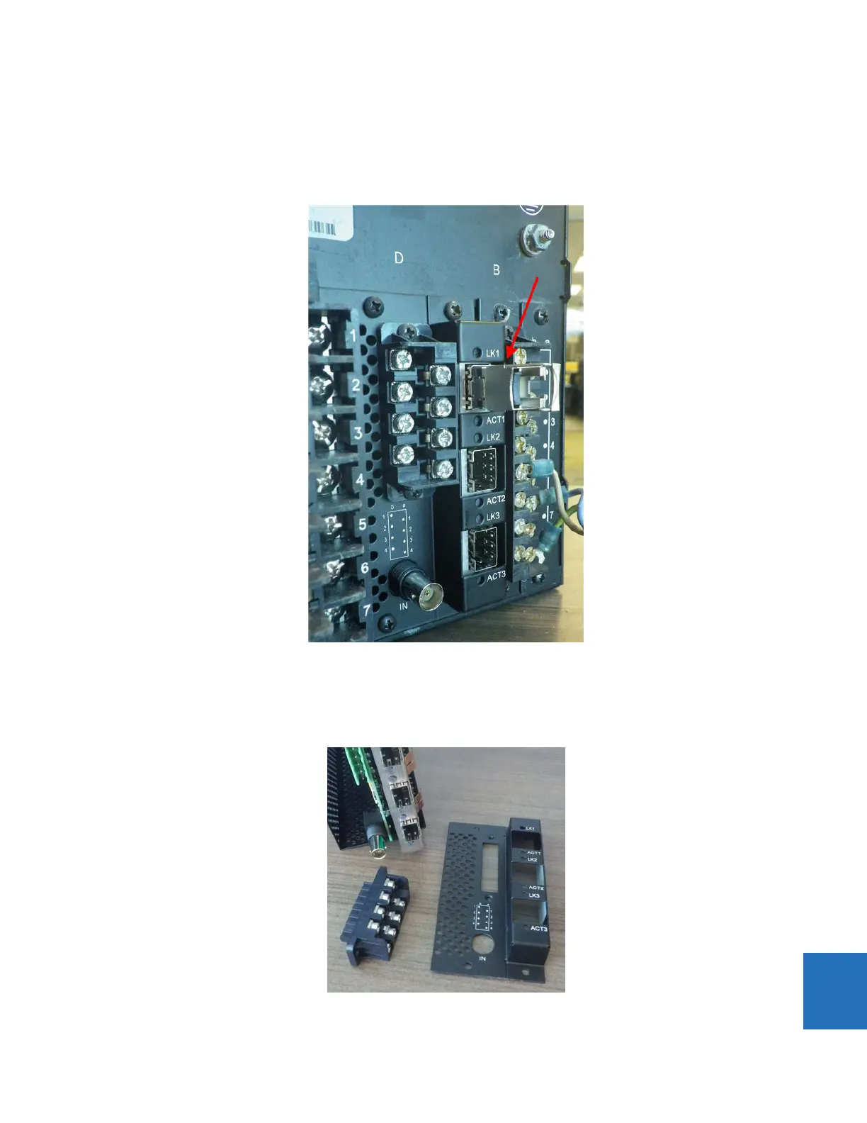
Figure 10-22: Remove silver SFP connector (shown here under LK1 label)
2. At the front of the relay, insert the new CPU module in the second slot. The new CPU has two connection slots on the
front. Ensure that the RS485 connector and the black cover plate are not on the back of the CPU module before sliding
the module into the front of the relay.
Figure 10-23: Rear of a CPU module before insertion without RS485 connector or cover plate