CHAPTER 3: INSTALLATION DIRECT INPUT AND OUTPUT COMMUNICATIONS
C70 CAPACITOR BANK PROTECTION AND CONTROL SYSTEM – INSTRUCTION MANUAL 3-47
3
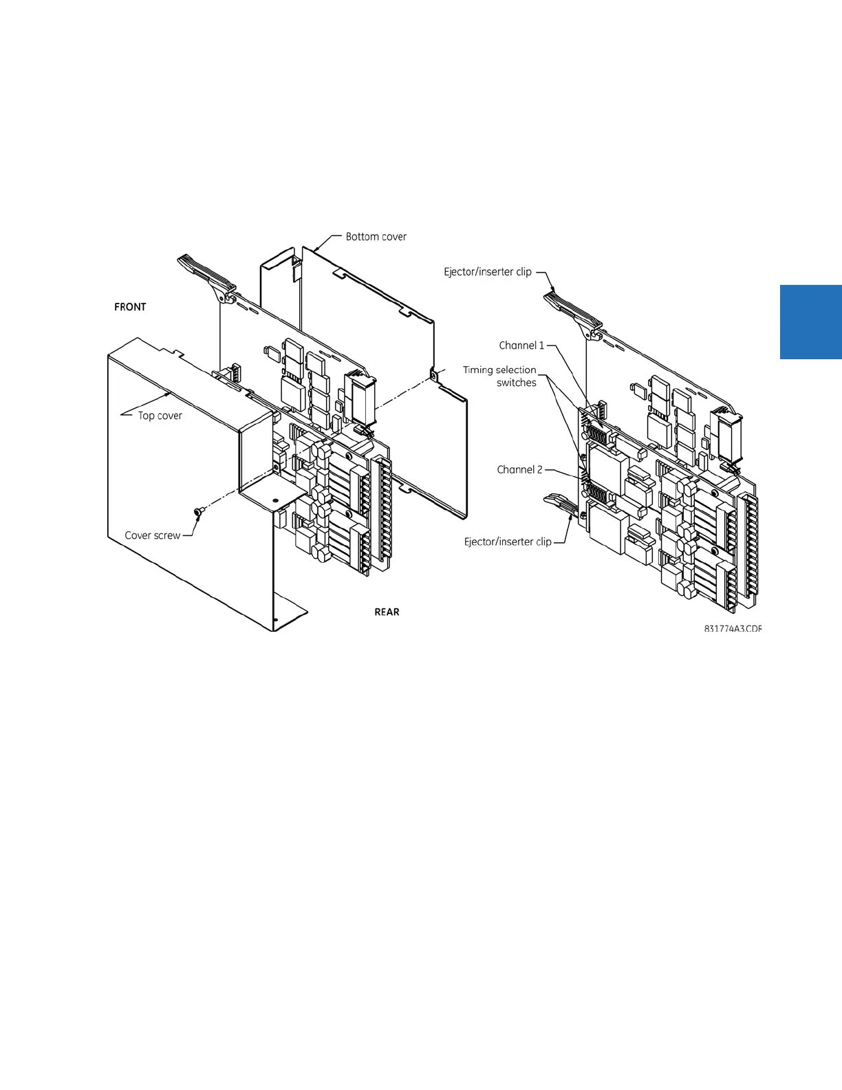
5. Set the timing selection switches (channels 1 and 2) to the required timing modes (see description earlier).
6. Replace the top cover and the cover screw.
7. Re-insert the IEEE C37.94 module. Take care to ensure that the correct module type is inserted into the correct slot
position. The ejector/inserter clips located at the top and at the bottom of each module must be in the disengaged
position as the module is inserted smoothly into the slot. Once the clips have cleared the raised edge of the chassis,
engage the clips simultaneously. When the clips have locked into position, the module is inserted fully.
Figure 3-52: IEEE C37.94 timing selection switch setting
Modules shipped since January 2012 have status LEDs that indicate the status of the DIP switches, as shown in the
following figure.