Getting Started
1-44
LOGIQ E9
–
User Guide
Direction 5454884-100 English
Rev. 1
Displaying the Guidezone (continued)
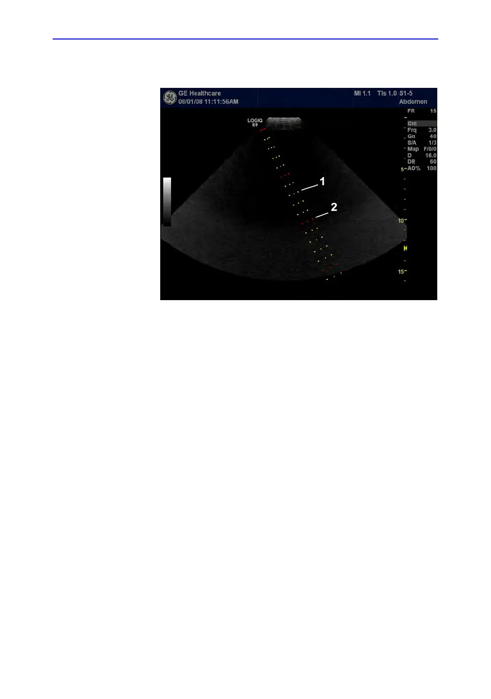
Figure 1-19. Biopsy Guidezones for the S1-5 Probe
1. 1 cm increments
2. 5 cm increments
The biopsy guidezone represents a path of the needle. The dots
which make up the guidezones is the depth readout where:
• Yellow represent 1 cm increments.
• Red represents 5 cm increments.
The display should be carefully monitored during a biopsy for
any needle deviation from the center line or guidezone.
Before scanning, verify the needle can be visualized within the
imaging plane. User appropriate needle length to reach target
area.