GE PROPRIETARY TO GE
D
IRECTION 5308917-100, REVISION 8 LOGIQ P3 SERVICE MANUAL
8-26 Section 8-2 - Disassembly/Re-assembly of LOGIQ P3
8-2-12 Optical Trackball Assy (FRU P/N: 5315029)
This is a description on how to remove and replace the Optical Trackball Assembly.
8-2-12-1 Tools
• Common phillips screwdrivers
8-2-12-2 Needed Manpower
• 1 person, 10 minutes
8-2-12-3 Preparations
• Shutdown the system and switch off the main Circuit Breaker at the bottom rear side of the system.
8-2-12-4 Removal procedure
1) Remove Keyboard Assembly. Refer section 8-2-7 on page 10.
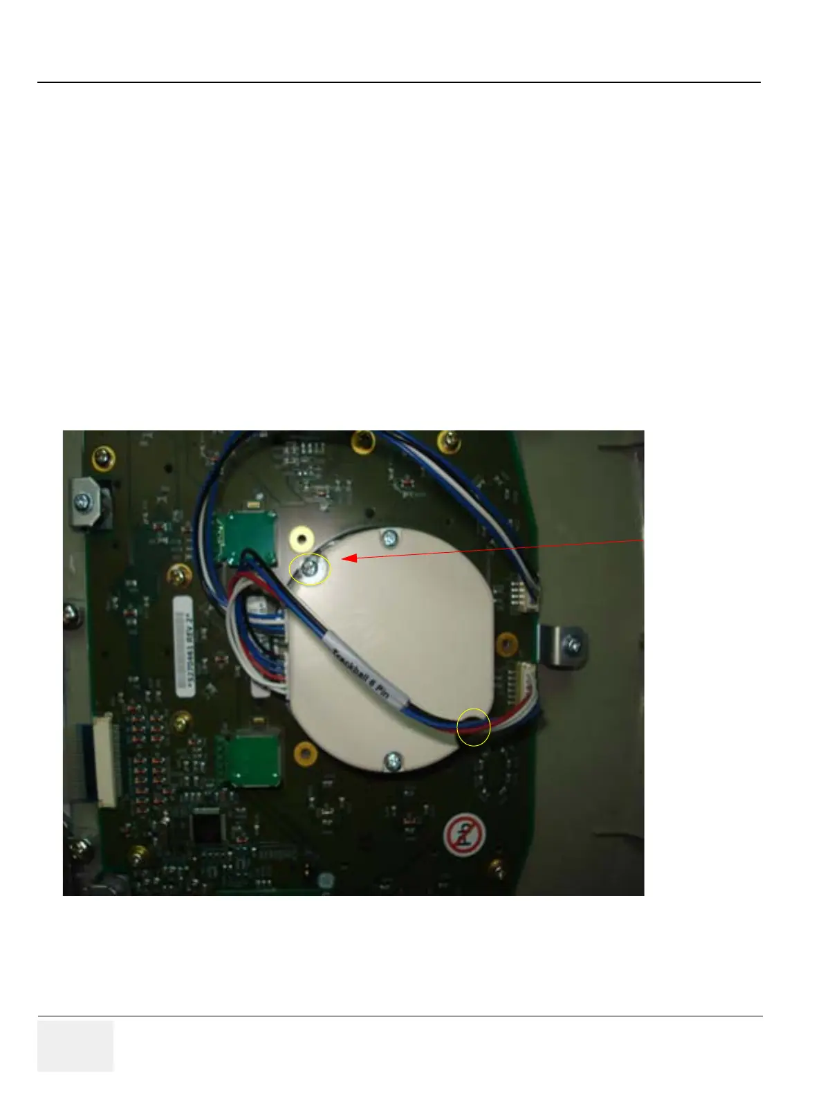
2) Unfasten the 2 screws(A,B) holding the trackball bracket (circled in Yellow color in Figure 8-29 on
page 8-26 )
3) Remove Trackball assembly with Trackball Interface cable. Refer Figure 8-29 on page 8-26
Figure 8-29 Optical Trackball Assembly
8-2-12-5 Mounting procedure
1.) Install the new parts in the reverse order of removal.

 Loading...


