EasyManuals Logo

GE LOGIQ P6 Service Manual

GE LOGIQ P6
478 pages
To Next Page IconTo Next Page
To Previous Page IconTo Previous Page
Page #230 background imageLoading...
Page #230 background image
GE HEALTHCARE
DIRECTION 5245279, REVISION 3 LOGIQ™ P6/P6 PRO SERVICE MANUAL
8 - 10 Section 8-2 - DISASSEMBLY/RE-ASSEMBLY
8-2-3 17 INCH LCDMON ASSY
8-2-3-1 Tools
•L wrench
8-2-3-2 Preparation
Shut down the system and switch off the main breaker
8-2-3-3 17" LCDMON ASSY Replace Procedure
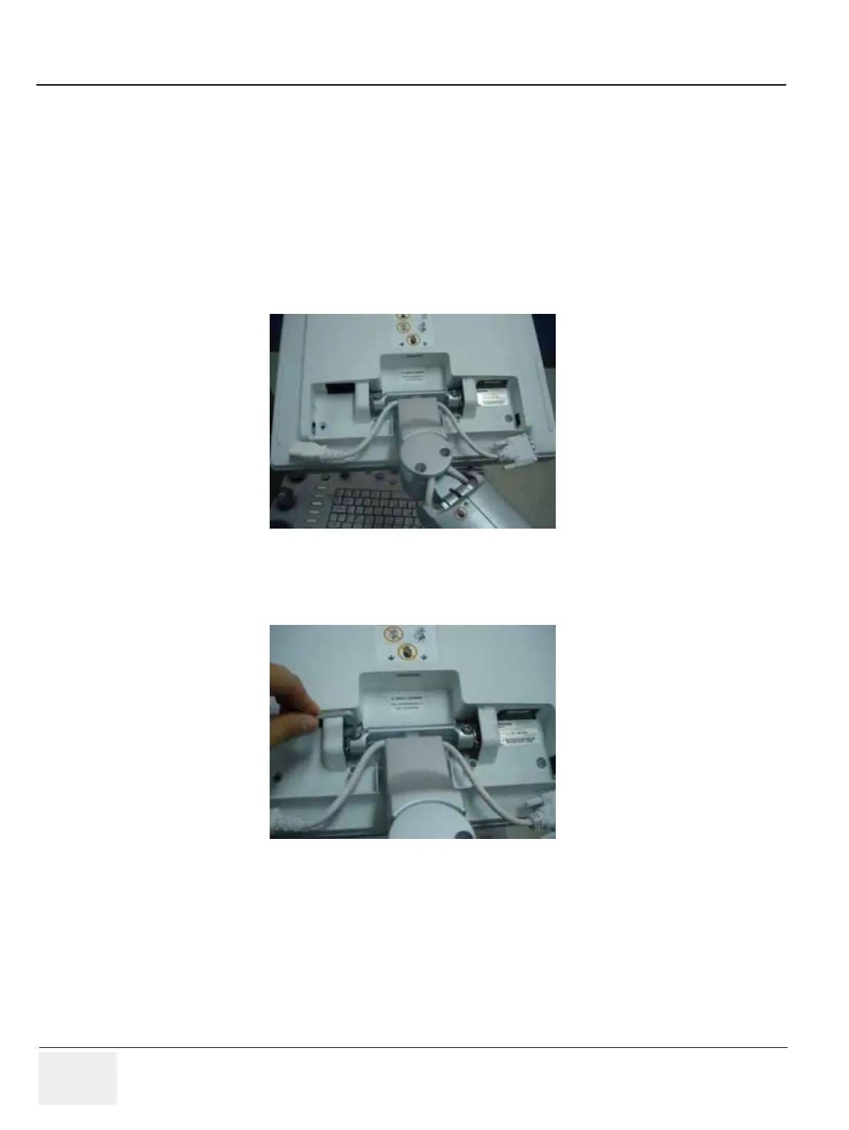
1.) Remove the LCD Cable cover. Refer to the figure below.
2.) Unscrew 1 screw (2306565,BH M4 x 16WHT) to remove the power code bracket assembled under
the LCD cable cover. Refer to the figure below.
3.) Disconnect power and DVI cable.
Figure 8-14 Removing the LCD Cable Cover
Figure 8-15 Removing the power code bracket

Table of Contents

Other manuals for GE LOGIQ P6

Questions and Answers:

Question and Answer IconNeed help?

Do you have a question about the GE LOGIQ P6 and is the answer not in the manual?

GE LOGIQ P6 Specifications

General IconGeneral
TypeUltrasound System
ConnectivityDICOM, USB, Ethernet
ApplicationsObstetrics, Gynecology, Vascular, Cardiology, Musculoskeletal
ProbesConvex, Linear, Phased Array
Imaging ModesB-mode, M-Mode, Color Doppler, Power Doppler, Pulsed Wave Doppler
PortabilityMobile
Transducer Ports3 active ports

Related product manuals