GE HEALTHCARE
DIRECTION 5245279, REVISION 3 LOGIQ™ P6/P6 PRO SERVICE MANUAL
Section 8-2 - DISASSEMBLY/RE-ASSEMBLY 8 - 11
8-2-3-3 17" LCDMON ASSY Replace Procedure (cont’d)
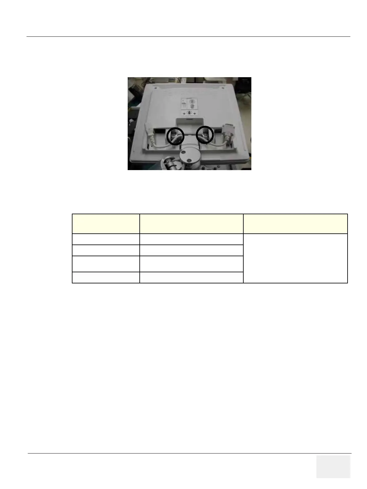
4.) Unscrew 2 screw (GEPN:5177684, HSH M5X20WHT) and Remove Spring(GEPN:5177655). Refer
to the figure below.
5.) Perform the following functional tests. If all are successful, include the debrief script provided below.
8-2-3-4 Mounting Procedure
Install the new parts in the reverse order of removal
Figure 8-16 Removing Spring
Table 8-4 Functional Tests
Service Manual
Section Functional Test / Diagnostic Test Debrief Script
Section 4-3-1
Power On/Boot Up
“Service Manual, Direction
5245279, Rev 3+, Section 8-2-3. Equipment
passed all required tests and is ready for use. “
Section 4-3-2
Power Off / Shutdown
Section 4-6-1
17" LCDMON II Assy & LCD Panel with filter
Function Validation Procedure
Section 10-5-2
Functional Checks (See Also Chapter 4)

 Loading...


