EasyManuals Logo

GE LOGIQ P6 Service Manual

GE LOGIQ P6
478 pages
To Next Page IconTo Next Page
To Previous Page IconTo Previous Page
Page #235 background imageLoading...
Page #235 background image
GE HEALTHCARE
DIRECTION 5245279, REVISION 3 LOGIQ™ P6/P6 PRO SERVICE MANUAL
Section 8-2 - DISASSEMBLY/RE-ASSEMBLY 8 - 15
8-2-4-3 Removal procedure (cont’d)
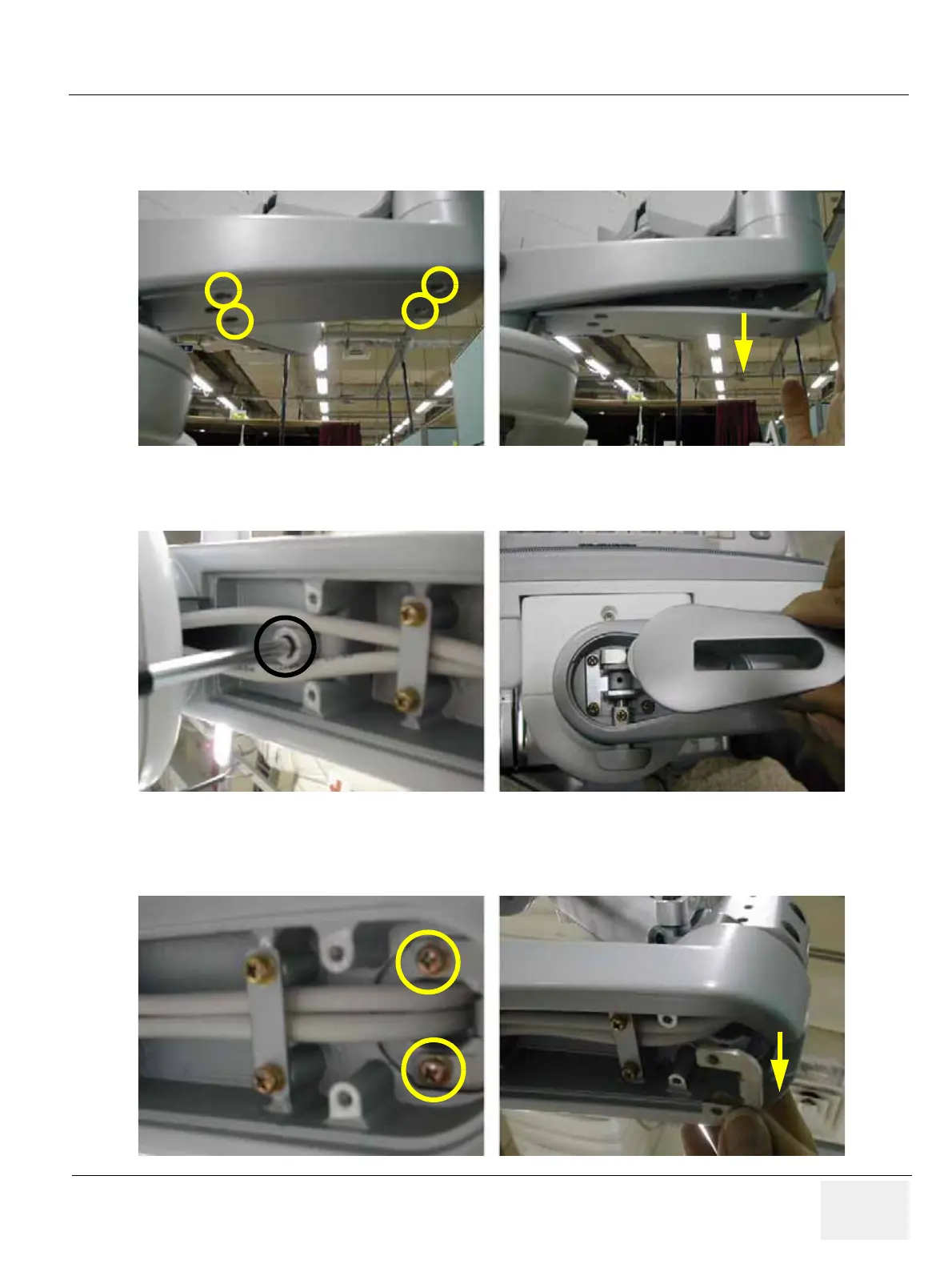
9.) Unscrew 4 screws (2159634, BH M4x10 WHT) to remove the Arm bottom cover. Refer to the figure
below.
10.)Unscrew 1 screw (2329677, TAP M4X16) to remove the Lock cover. Refer to the figure below.
11.)Unscrew 2 screws (2159625, PH M4x8 W/SP) to remove the Lower arm guide bracket. Refer to the
figure below.
Figure 8-25 Removing the Arm bottom cover
Figure 8-26 Removing the Lock cover
Figure 8-27 Removing the the Lower arm guide bracket

Table of Contents

Other manuals for GE LOGIQ P6

Questions and Answers:

Question and Answer IconNeed help?

Do you have a question about the GE LOGIQ P6 and is the answer not in the manual?

GE LOGIQ P6 Specifications

General IconGeneral
TypeUltrasound System
ConnectivityDICOM, USB, Ethernet
ApplicationsObstetrics, Gynecology, Vascular, Cardiology, Musculoskeletal
ProbesConvex, Linear, Phased Array
Imaging ModesB-mode, M-Mode, Color Doppler, Power Doppler, Pulsed Wave Doppler
PortabilityMobile
Transducer Ports3 active ports

Related product manuals