GE HEALTHCARE
DIRECTION 5245279, REVISION 3 LOGIQ™ P6/P6 PRO SERVICE MANUAL
8 - 20 Section 8-2 - DISASSEMBLY/RE-ASSEMBLY
8-2-4-3 Removal procedure (cont’d)
20.)Perform the following functional tests. If all are successful, include the debrief script provided below.
8-2-4-4 Assembly procedure
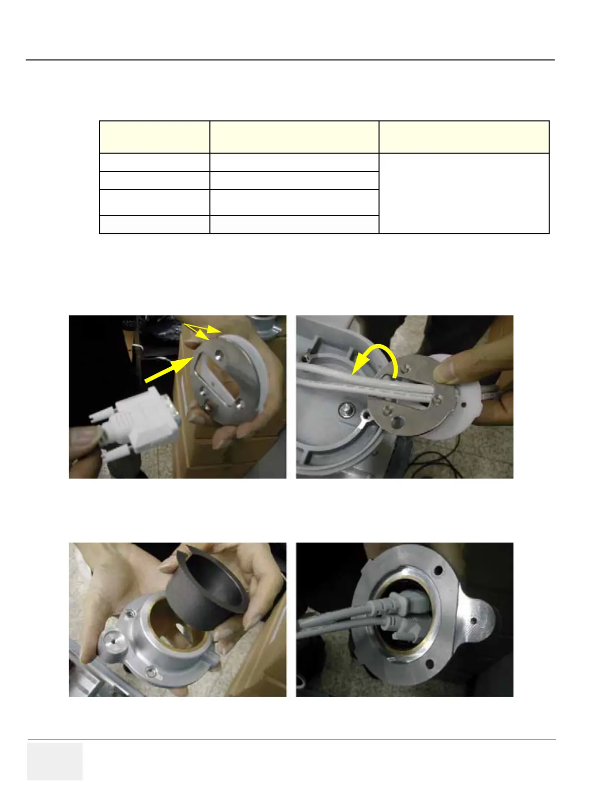
1.) Insert two of the flexible arm stoppers (A+B) to the Power Cable and DVI cable in the Order
illustrated on the figure below. Make sure that chamfered shape of the flexible Arm stopper should
face inside. Refer to the figure below.
2.) Insert oilless bush into the flexible arm neck pipe and insert two cables into the flexible arm neck
pipe. Refer to the figure below.
Table 8-5 Functional Tests
Service Manual
Section Functional Test / Diagnostic Test Debrief Script
Section 4-3-1
Power On/Boot Up
“Service Manual, Direction
5245279, Rev 3+, Section 8-2-4. Equipment
passed all required tests and is ready for use. “
Section 4-3-2
Power Off / Shutdown
Section 4-8-6
New articulation arm with cover Function
Validation Procedure
Section 10-5-5
Physical Inspection
Figure 8-36 Inserting cables to the flexible arm stopper
Figure 8-37 Inserting the oilless bush
Flexible Arm Stopper

 Loading...


