GE HEALTHCARE
DIRECTION 5245279, REVISION 3 LOGIQ™ P6/P6 PRO SERVICE MANUAL
8 - 44 Section 8-2 - DISASSEMBLY/RE-ASSEMBLY
8-2-11-3 Removal procedure (cont’d)
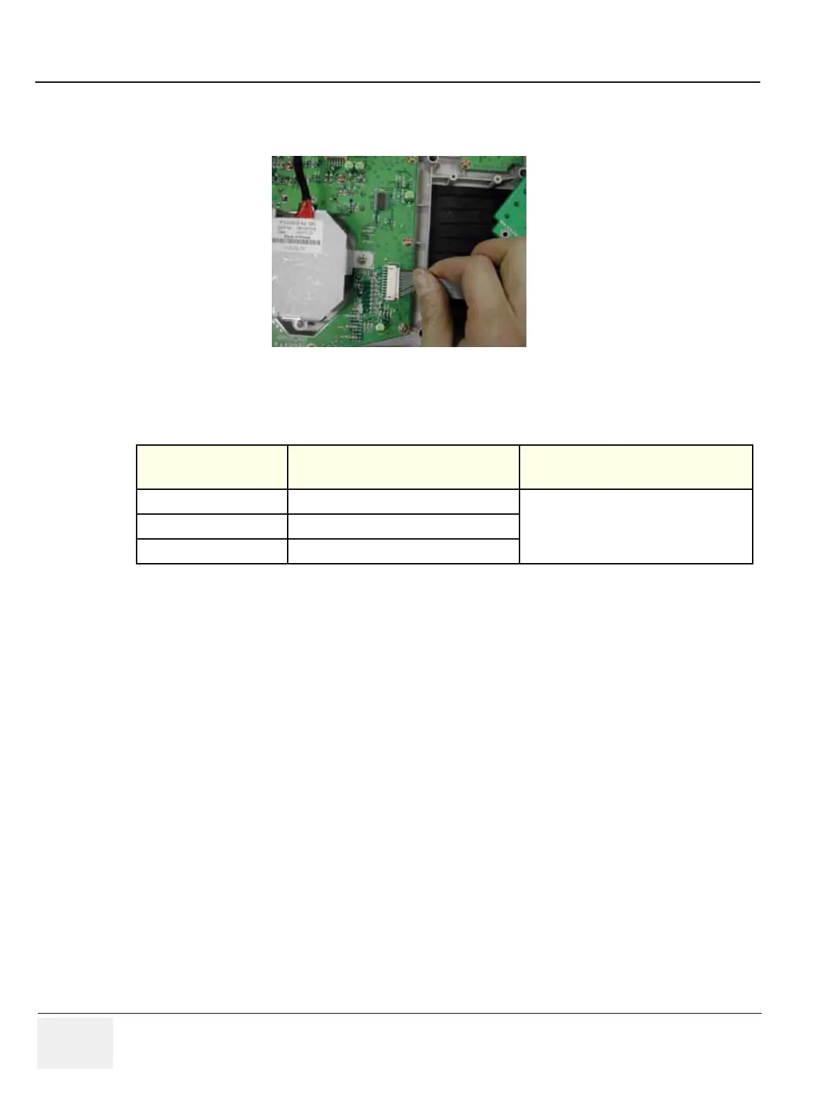
4.) Disconnect 1 connector from the PCB. Refer to the figure below.
5.) Perform the following functional tests. If all are successful, include the debrief script provided below.
8-2-11-4 Mounting Procedure
Install the new parts in the reverse order of removal.
Figure 8-83 TGC Key Connector
Table 8-12 Functional Tests
Service Manual
Section
Functional Test / Diagnostic Test Debrief Script
Section 4-3-1
Power On/Boot Up
“Service Manual, Direction
5245279, Rev 3+, Section 8-2-11. Equipment
passed all required tests and is ready for use. “
Section 4-3-2
Power Off / Shutdown
Section 4-7-6
TGC key assy / TGC Knob Set validation

 Loading...


