GE HEALTHCARE
DIRECTION 5245279, REVISION 3 LOGIQ™ P6/P6 PRO SERVICE MANUAL
Section 8-2 - DISASSEMBLY/RE-ASSEMBLY 8 - 91
8-2-42-3 Removal procedure (cont’d)
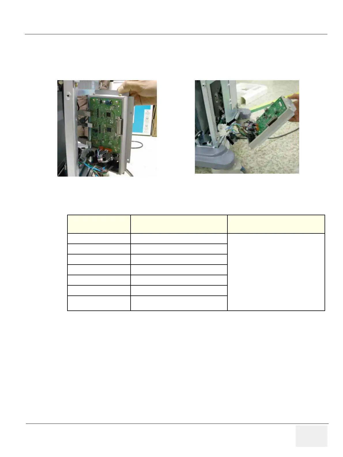
5.) Disconnect three (3) USB connectors or 5 USB connectors from the rear panel and 2 AC power
connector. The 4D controller USB and ECG USB connector also connect to this rear paenl PWA.
Refer to the Figure 8-135.
6.) Perform the following functional tests. If all are successful, include the debrief script provided below.
8-2-42-4 Mounting Procedure
Install the new parts in the reverse order of removal.
Figure 8-135 Open Rear Panel
Table 8-43 Functional Tests
Service Manual
Section
Functional Test / Diagnostic Test Debrief Script
Section 4-3-1
Power On/Boot Up
“Service Manual, Direction
5245279, Rev 3+, Section 8-2-42. Equipment
passed all required tests and is ready for use. “
Section 4-3-2
Power Off / Shutdown
Section 4-9-15
ARPII Assy Function Validation Procedure
Section 4-5
Peripheral Checks
Section 10-5-2-2
Peripheral/Option Checks
Section 10-5-5
Probe Maintenance
Section 10-6-3
Outlet Test - Wiring Arrangement - USA &
Canada

 Loading...


