GE HEALTHCARE
DIRECTION 5245279, REVISION 3 LOGIQ™ P6/P6 PRO SERVICE MANUAL
8 - 164 Section 8-7 - Mechanical Option Installation instruction
8-7-1-4 Assembly procedure (cont’d)
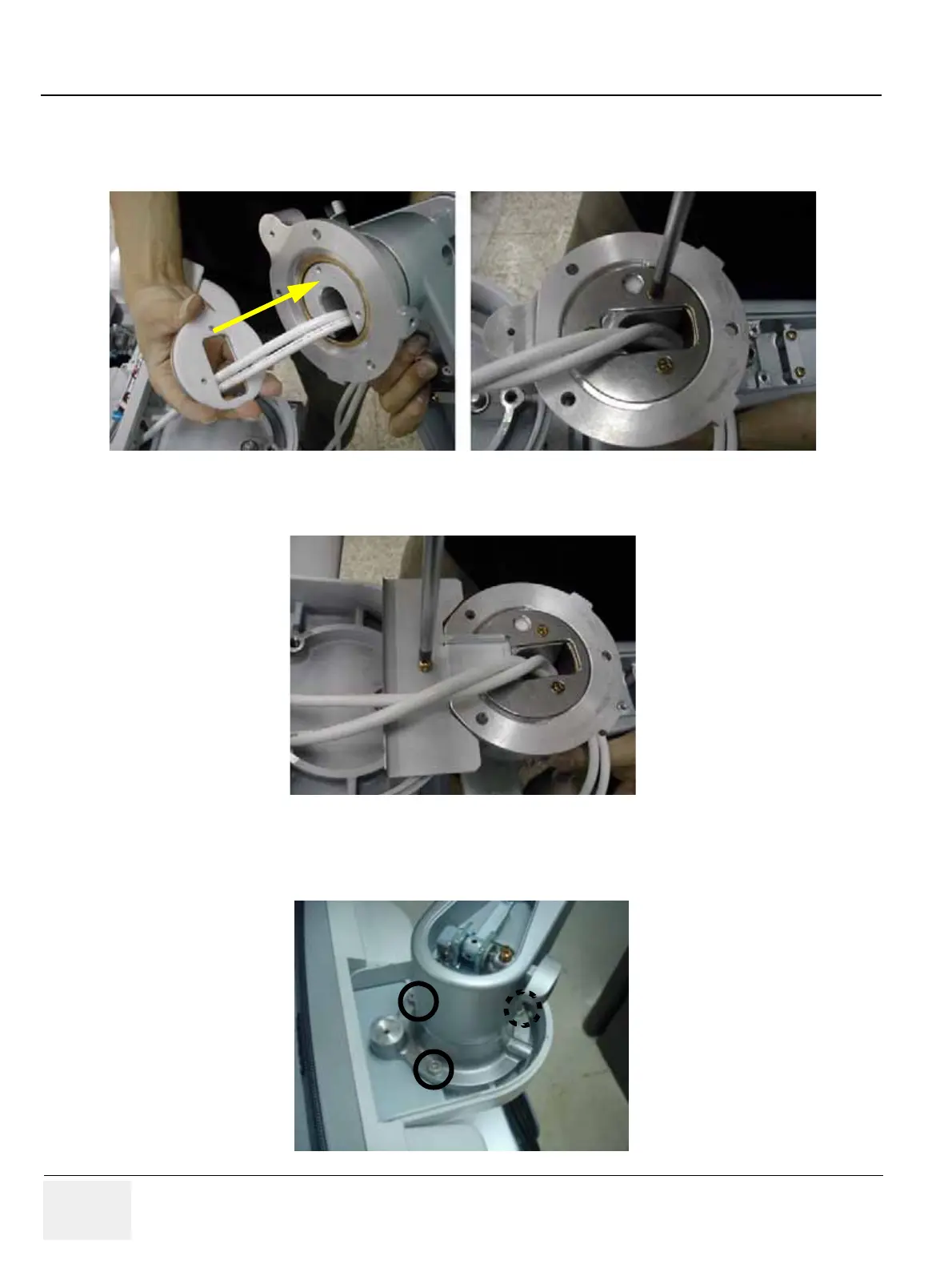
4.) Screw 3 screws (2373562, FH M4X10 YEL) to fix the flexible arm stopper after adjusting the holes.
Refer to the figure below.
5.) Screw 1 screw (2159625, PH M4X8 W/SP) to install OP bracket. Refer to the figure below.
6.) Screw 3 screws (5327646, HSH M6X16 WHT) to install the arm neck pipe. Make sure place DVI
cable be on the right side, power cable on the left side. Refer to the figure below.
Figure 8-253 Fixing the flexible arm stopper
Figure 8-254 Installing OP Bracket
Figure 8-255 Assembling the arm neck pipe

 Loading...


