EasyManuals Logo

GE LOGIQ P6 Service Manual

GE LOGIQ P6
478 pages
To Next Page IconTo Next Page
To Previous Page IconTo Previous Page
Page #399 background imageLoading...
Page #399 background image
GE HEALTHCARE
DIRECTION 5245279, REVISION 3 LOGIQ™ P6/P6 PRO SERVICE MANUAL
Section 8-7 - Mechanical Option Installation instruction 8 - 179
8-7-6 BW Printer Fixture Keyboard installation (cont’d)
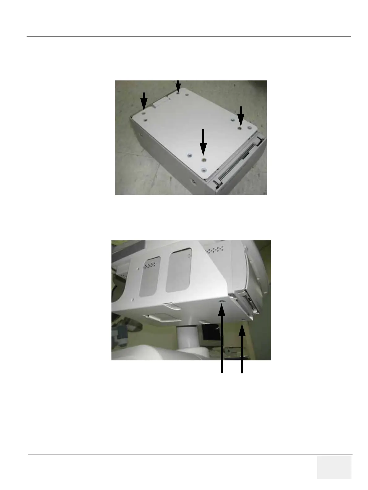
4.) Fix the BW printer base bracket to the BW Printer by screwing 4 screws(2306562, FH M3x6 YEL)
(1-4). Refer to the figure below.
5.) Slide and place the BW printer with base bracket to the BW printer bracket and screw 2 screws
(5178673, FH M4x6 WHT) (1-2) to fix it. Refer to the figure below.
Figure 8-286 BW Printer Fixture Keyboard installation
Figure 8-287 BW Printer Fixture Keyboard installation
base bracket
(1)
(2)
(3)
(4)
(1)
(2)

Table of Contents

Other manuals for GE LOGIQ P6

Questions and Answers:

Question and Answer IconNeed help?

Do you have a question about the GE LOGIQ P6 and is the answer not in the manual?

GE LOGIQ P6 Specifications

General IconGeneral
TypeUltrasound System
ConnectivityDICOM, USB, Ethernet
ApplicationsObstetrics, Gynecology, Vascular, Cardiology, Musculoskeletal
ProbesConvex, Linear, Phased Array
Imaging ModesB-mode, M-Mode, Color Doppler, Power Doppler, Pulsed Wave Doppler
PortabilityMobile
Transducer Ports3 active ports

Related product manuals