GE Multilin F650 Digital Bay Controller 9-17
9 COMMISSIONING 9.13 UNDERVOLTAGE ELEMENTS (27P, 27X)
9
9.13UNDERVOLTAGE ELEMENTS (27P, 27X) 9.13.1 27P ELEMENT
Set the relay to trip for the protection element being tested. Configure any of the outputs to be activated only by the
protection element being tested.
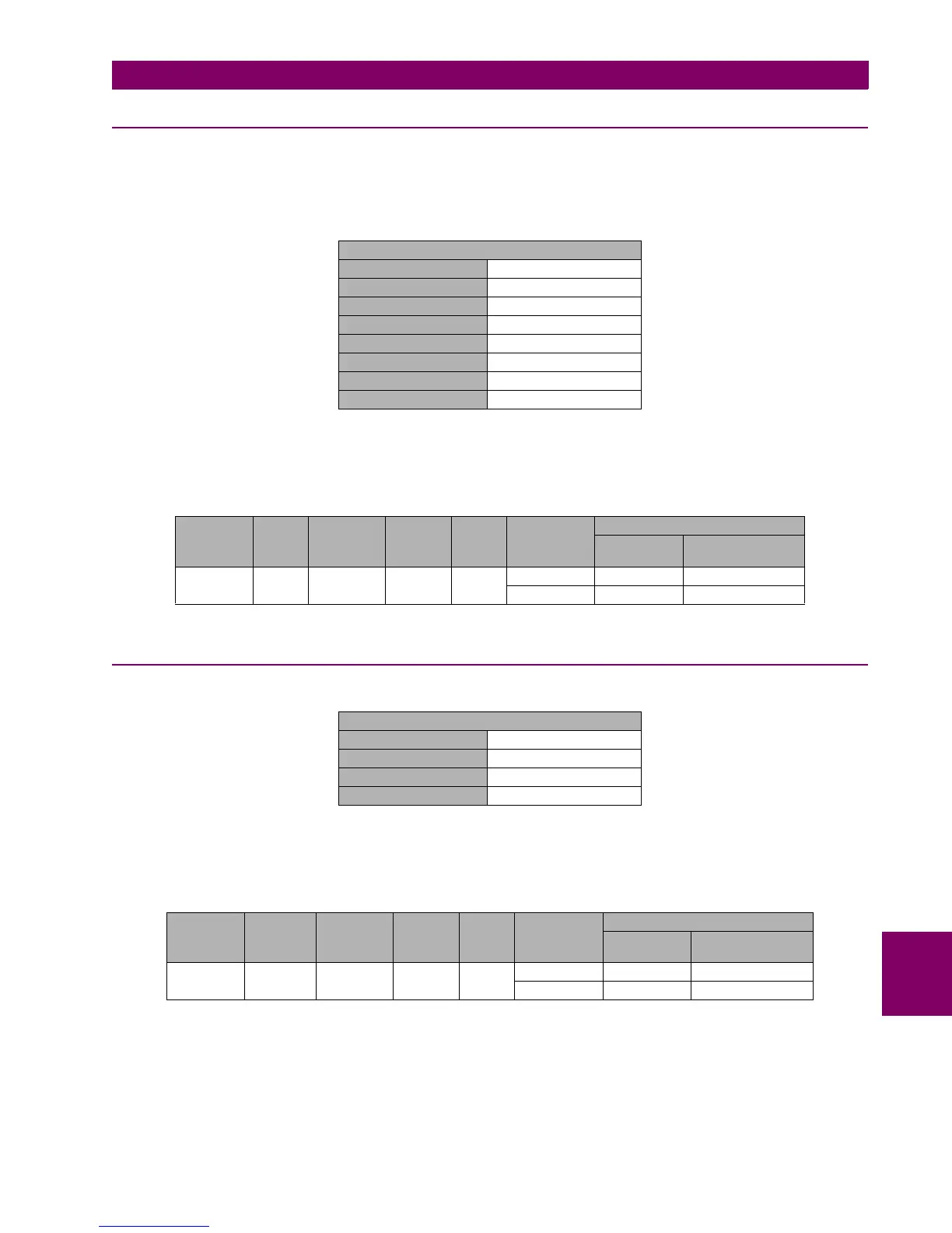
Set the relay as follows:
Apply voltage as indicated on the table over the undervoltage setting level and verify that the relay does not trip.
Decrease voltage level gradually and verify that the relay trips for the set voltage (with an admissible error of 5%).
9.13.2 27X ELEMENT
Apply voltage as indicated on the table over the undervoltage setting level and verify that the relay does not trip.
Decrease voltage level gradually and verify that the relay trips for the set voltage (with an admissible error of 5%).
PHASE UV (27P)
Function ENABLED
Mode PHASE-GROUND
Pickup Level 50 V
Curve DEFINITE TIME
Delay 2.00 sec
Minimum Voltage 30 V
Logic ANY PHASE
Supervised by 52 DISABLED
ELEMENT PHASE CURVE PICKUP
LEVEL
DELAY APPLIED
VOLTAGE
TRIPPING TIMES (S)
THEORETICA
L
ADMISSIBLE
27P VI DEFINITE
TIME
50 V 2 55 V NO TRIP NA
45 V 2.000 sec [2.000 – 2.100]
AUXILIARY UV (27X)
Function ENABLED
Pickup Level 50 V
Curve DEFINITE TIME
Delay 2.00 sec
ELEMENT INPUT CURVE PICKUP
LEVEL
DELAY APPLIED
VOLTAGE
TRIPPING TIME (S)
THEORETICA
L
ADMISSIBLE
27X VX DEFINITE
TIME
50 V 2 55 V NO TRIP NA
45 V 2.000 sec [2.000 – 2.100]

 Loading...


