C-2 F650 Digital Bay Controller GE Multilin
C.1 DNP 3.0 PROTOCOL FOR F650 APPENDIX C
C
1. Physical Port: The F650 supports the Distributed Network Protocol (DNP) version 3.0. The F650 can be used as a
DNP slave device connected up to three DNP masters (usually RTUs or SCADA master stations).. The Physical
Port setting is used to select the communications port assigned to the DNP protocol for a specific logical DNP slave
device of F650.. When this setting is set to NETWORK, the DNP protocol can be used over either TCP/IP or UDP/
IP.
2. Address: This setting is the DNP slave address. This number identifies de F650 on a DNP communications link.
Each logical DNP slave should be assigned a unique address.
3-22. IP Addr Client x Oct x: this setting is one of four octets of an IP address. The F650 relay can respond to a
maximum of 5 specific DNP masters (not in the same time). To set the IP address of DNP master it is necessary to
set four octets (e.g. to set the IP address of the first DNP master to 192.168.48.125, you should set IP Addr Client1
Oct1 = 192, IP Addr Client1 Oct2 = 168, IP Addr Client1 Oct3 = 48, IP Addr Client1 Oct4 = 125).
23. TCP/UDP Port: TCP/UDP port number for the case of DNP3 communication being performed through the
Ethernet.
24. Unsol Resp Function: ENABLED, if unsolicited responses are allowed, and DISABLED otherwise.
25. Unsol Resp TimeOut: sets the time the F650 waits for a DNP master to confirm an unsolicited response.
26. Unsol Resp Max Ret: This setting determines the number of times the F650 will retransmit an unsolicited response
without receiving a confirmation from the master. Once this limit has been exceeded, the unsolicited response will
continue to be sent at larger interval. This interval is called unsolicited offline interval and is fixed at 10 minutes.
27. Unsol Resp Dest Adr: This setting is DNP address to which all unsolicited responses are sent. The IP address to
which unsolicited responses are sent is determined by the F650 from either the current DNP TCP connection or the
most recent UDP message.
28-32. Scale Factor: These settings are numbers used to scale Analog Input point values. These settings group the F650
Analog Input data into types: current, voltage, power, energy, and other. Each setting represents the scale factor for
all Analog Input points of that type. For example, if the Voltage Scale Factor is set to a value of 1000, all DNP
Analog Input points that are voltages will be returned with the values 1000 times smaller (e.g. a value 72000 V on
the F650 will be returned as 72). These settings are useful when Analog Input values must be adjusted to fit within
certain ranges in DNP masters. Note that a scale factor of 0.1 is equivalent to a multiplier of 10 (i.e. the value will be
10 times larger).
33-37. Deadband: These settings are the values used by the F650 to determine when to trigger unsolicited responses
containing Analog Input data. These settings group the F650 Analog Input data into types: current, voltage, power,
energy, and other. Each setting represents the default deadband value for all Analog Input points of that type. For
example, in order to trigger unsolicited responses from the F650 when any current values change by 15 A, the
Current Deadband setting should be set to 15. Note that these settings are the default values of the deadbands.
DNP object 34 points can be used to change deadband values, from the default, for each individual DNP Analog
Input point. Whenever power is removed and re-applied to the F650, the default deadbands will be in effect.
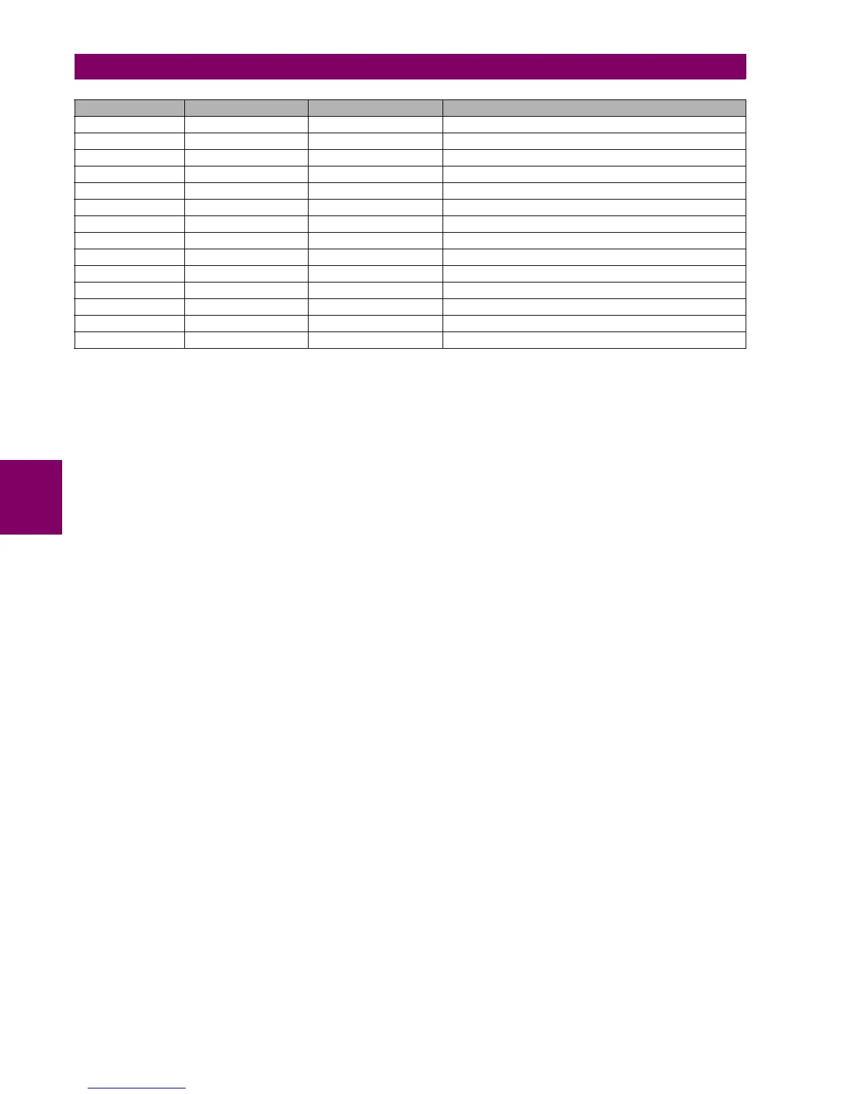
SETTING NO SETTING NAME DEFAULT VALUE RANGE
35 Power Deadband 30000 0 to 65535, step 1
36 Energy Deadband 30000 0 to 65535, step 1
37 Other Deadband 30000 0 to 65535, step 1
38 Msg Fragment Size 240 30 to 2048, step 1
39 Binary Input Block1 CTL EVENTS 1-16 See the explanation below
40 Binary Input Block2 CTL EVENTS 17-32 See the explanation below
41 Binary Input Block3 CTL EVENTS 33-48 See the explanation below
42 Binary Input Block4 CTL EVENTS 49-64 See the explanation below
43 Binary Input Block5 CTL EVENTS 65-80 See the explanation below
44 Binary Input Block6 CTL EVENTS 81-96 See the explanation below
45 Binary Input Block7 CTL EVENTS 97-112 See the explanation below
46 Binary Input Block8 CTL EVENTS 113-128 See the explanation below
47 Binary Input Block9 SWITCHGEAR 1-8 See the explanation below
48 Binary Input Block10 SWITCHGEAR 9-16 See the explanation below

 Loading...


