GEK-113032A W650 Wind Generator Protection System A-5
APPENDIX A A.1 LOGIC OPERANDS
A
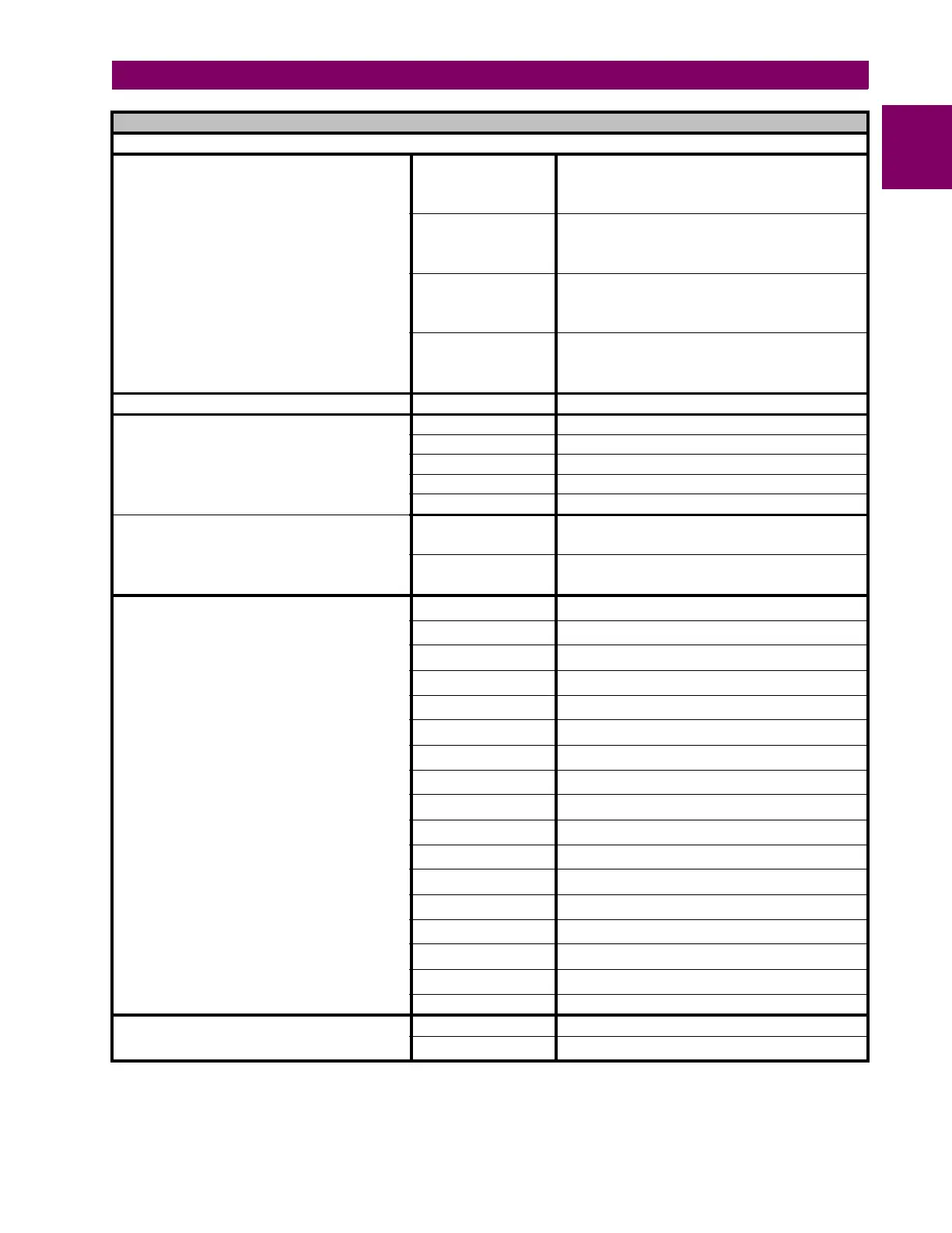
OPERANDS - 650 - MODEL FX - GX
INTERNAL SYSTEM STATUS (CONT.)
LEDS HMI (16 elements)
LED 12
Programmable LED 12 status: Green colour. Not
latched. Latching possibility via PLC. Reset by
hardware (ESC) and programmable (LED RESET
INPUT)
LED 13
Programmable LED 13 status: Green colour. Not
latched. Latching possibility via PLC. Reset by
hardware (ESC) and programmable (LED RESET
INPUT)
LED 14
Programmable LED 14 status: Green colour. Not
latched. Latching possibility via PLC. Reset by
hardware (ESC) and programmable (LED RESET
INPUT)
LED 15
Programmable LED 15 status: Green colour. Not
latched. Latching possibility via PLC. Reset by
hardware (ESC) and programmable (LED RESET
INPUT)
LEDs reset input (programmable) LED RESET INPUT Programmable input for remote LED reset
Programmable Keypad Status (HMI)
I Key I key operation (Programmable signal via PLC)
O Key O key operation (Programmable signal via PLC)
* Key * key operation (Programmable signal via PLC)
F1 Key F1 key operation (Programmable signal via PLC)
F2 Key F2 key operation (Programmable signal via PLC)
LOCAL/REMOTE Operation status LEDs
LOCAL OPERATION
MODE
Local/remote status for operations 1 = Local, 0 =
Remote. Selectable only through the front pushbutton
(Hardware)
OPERATIONS
BLOCKED
Operations OFF status (1) Command execution block
(operations blocked both in local and remote mode)
Oscillography States
OSC DIG CHANNEL 1
Oscillography Digital channel 1 : (1) Active ; (0) Not
Active
OSC DIG CHANNEL 2
Oscillography Digital channel 2 : (1) Active ; (0) Not
Active
OSC DIG CHANNEL 3
Oscillography Digital channel 3 : (1) Active ; (0) Not
Active
OSC DIG CHANNEL 4
Oscillography Digital channel 4 : (1) Active ; (0) Not
Active
OSC DIG CHANNEL 5
Oscillography Digital channel 5 : (1) Active ; (0) Not
Active
OSC DIG CHANNEL 6
Oscillography Digital channel 6 : (1) Active ; (0) Not
Active
OSC DIG CHANNEL 7
Oscillography Digital channel 7 : (1) Active ; (0) Not
Active
OSC DIG CHANNEL 8
Oscillography Digital channel 8 : (1) Active ; (0) Not
Active
OSC DIG CHANNEL 9
Oscillography Digital channel 9 : (1) Active ; (0) Not
Active
OSC DIG CHANNEL 10
Oscillography Digital channel 10: (1) Active ; (0) Not
Active
OSC DIG CHANNEL 11
Oscillography Digital channel 11 : (1) Active ; (0) Not
Active
OSC DIG CHANNEL 12
Oscillography Digital channel 12 : (1) Active ; (0) Not
Active
OSC DIG CHANNEL 13
Oscillography Digital channel 13 : (1) Active ; (0) Not
Active
OSC DIG CHANNEL 14
Oscillography Digital channel 14 : (1) Active ; (0) Not
Active
OSC DIG CHANNEL 15
Oscillography Digital channel 15 : (1) Active ; (0) Not
Active
OSC DIG CHANNEL 16
Oscillography Digital channel 16 : (1) Active ; (0) Not
Active
OSCILLO TRIGGER Oscillo trigger activation (1) Active ; (0) Not active
Fault Report (Fault locator)
FAULT REPORT TRIGG Fault report trigger (1) Active ; (0) Not active
CLEAR FAULT
REPORTS
Fault report removal from HMI and ModBus (volatile
memory)
 Loading...


