GEK-113032A W650 Wind Generator Protection System E-15
APPENDIX E E.1 FACTORY DEFAULT SETTINGS
E
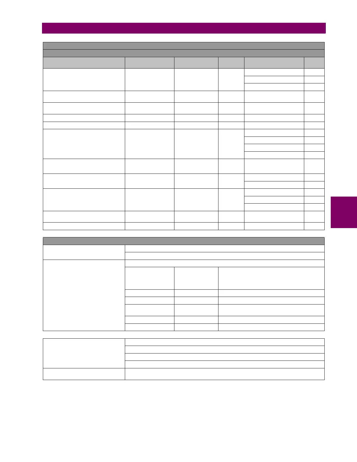
SETPOINT > INPUTS/OUTPUTS > CONTACT I/O >
BOARD F > BOARD G
SETTING DESCRIPTION NAME DEFAULT VALUE STEP RANGE
USER
VALUE
I/O board type (available only for CIO
modules)
I/O Board Type_H NONE N/A
[NONE,
16 INP + 8OUT,
8 INP + 8OUT + SUPV]
Input activation voltage threshold
Group A
Voltage Threshold
A_X
80 1 V [20 : 230]
Input activation voltage threshold
Group B
Voltage Threshold
B_X
80 1 V [20 : 230]
Debounce time for Group A Debounce Time A_X 15 1 ms [1 : 50]
Debounce time for Group B Debounce Time B_X 15 1 ms [1 : 50]
Input type
Input Type_X_CCY
(CCY)
POSITIVE N/A
[POSITIVE-EDGE,
NEGATIVE-EDGE,
POSITIVE,
NEGATIVE]
Input signal time delay
Delay Input
Time_X_CCY (CCY)
0 1 ms [0 : 60000]
Output logic type Output Logic_X_0Z POSITIVE N/A
[POSITIVE,
NEGATIVE]
Output type Output Type_X_0Z NORMAL N/A
[NORMAL,
PULSE,
LATCH]
Output pulse length
Pulse Output
Time_X_0Z
10000 1 ms [0 : 60000]
Snapshot event generation Snapshot Events ENABLED N/A [DISABLED – ENABLED]
NOTE 2: DESCRIPTION OF X, Y AND Z IN INPUT/OUTPUT BOARDS
X
F or G, , the I/O board name, depending on the Relay model.
F and G are internal Relay boards.
For the I/O board selection in the relay
model:
I/O BOARD TYPE
ASSOCIATED DIGIT
ENERVISTA 650
SETUP BOARD
SETTINGS
BOARD TYPE
0NONENone
1 16 INP+ 8 OUT Mixed
2
8 INP +8 OUT
+SUPV
Supervision
4 32 INP 32 digital inputs
5 16 INP + 8 ANA 16 digital inputs + 8 analog inputs
CCY
Is the name used for inputs in I/O boards
Mixed, 16 digital inputs: CC1….CC16
Supervision: 8 digital inputs: CC1,..., CC8
32 INP: 32 digital inputs; CC1,...,CC32
0Z
Is the name used for the different outputs in I/O boards, 8 outputs available for any of the two
types of board (01,…., 08)


 To Next Page