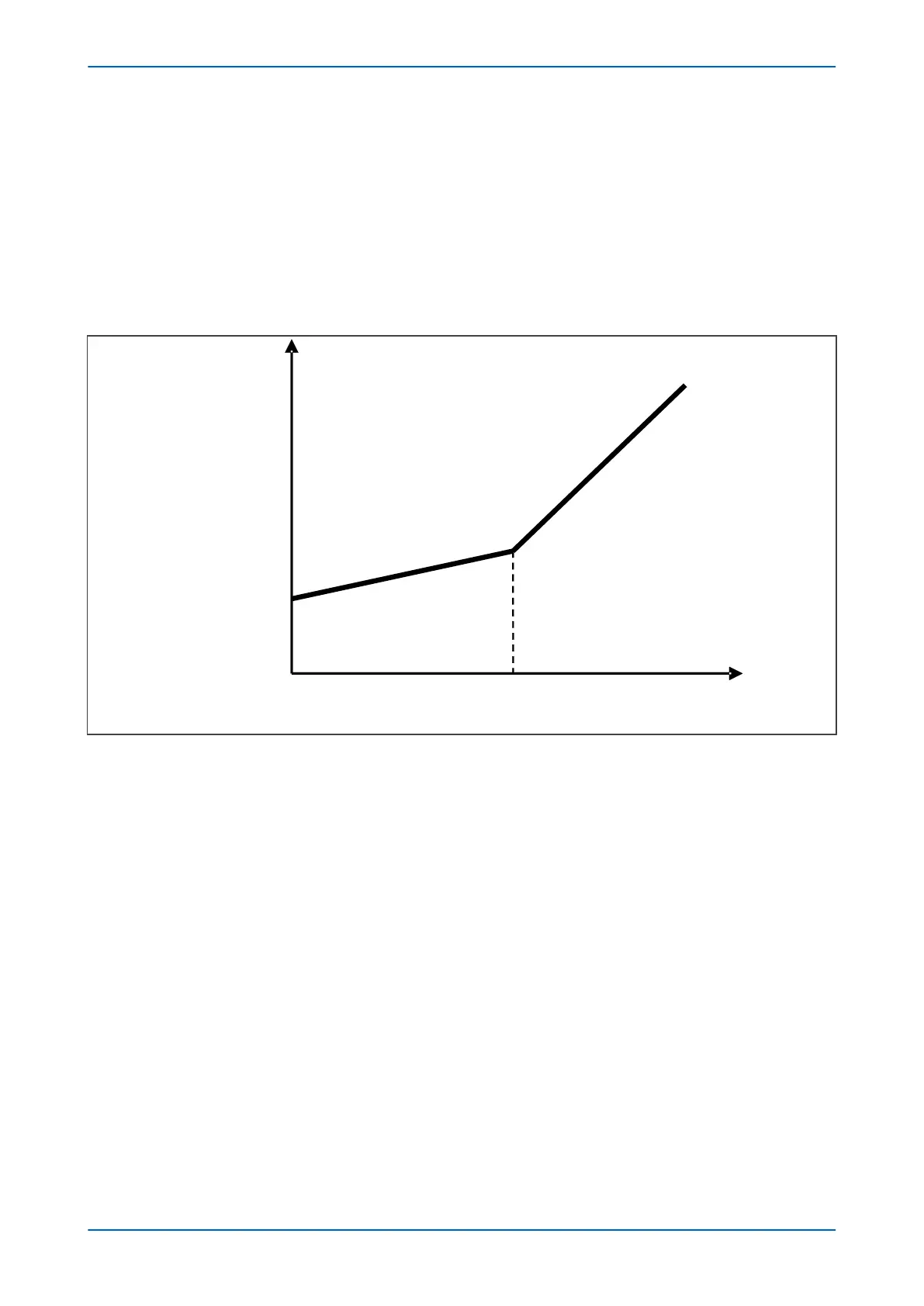
Where I
S1
, I
S2
, K
1
and K
2
ar
e setting values:
I
S1
: The minimum threshold for differential current;
I
S2
: The slope changing point (when the bias current is larger than this value, security is much more important than
reliability for differential protection);
K
1
: The slope of character when the fault is slight;
K
2
: The slope of character when the fault is severe.
The differential protection characteristic is shown below:
Tripping
Zone
Restrain
Zone
I
diff
I
bias
K
1
K
2
I
S1
I
N1
I
S2
E00762
Figure 33: Current differential discriminative criterion
The value of the minimum setting threshold for differential current (I
S1
) is required to be set higher than the
maximum unbalanced current due to measurement and calculation errors. Normally, I
S1
is set to be 0.1~0.5 p.u. to
avoid unbalanced current.
When the fault is low, the bias current value will be smaller as well. In this case, reliability is more important than
security, so that the slope of the character is smaller (Normally, K
1
is set to be 0.3~0.5).
On the other hand, when the fault is severe, bias current will be higher and security will become more important
than reliability (in this case, the CTs could be unbalanced and saturated, which can result in much higher
unbalanced current in I
diff
), so the protection will follow the character of slope K
2
, which has a much steeper slope
(k
2
=1.0~1.5).
All the settings should be set following the best balance between the security and reliability.
When the phase-differential protection issues a trip command, it sends a per-phase ‘differential intertrip’ signal to
the remote terminals to instruct them to trip their circuit breakers. This is to ensure that all ends of the protected
line trip, even for marginal fault conditions.
For grading with other protection, the phase differential protection trip signal can be time delayed using either a
definite time, or an inverse time characteristic. By default, the delay characteristic is set to definite time with a zero
second delay, resulting in instantaneous tripping.
Since differential and bias current calculations are made on a per-phase basis, the values vary on a per-phase
basis. For optimum stability the highest value of the three-phase bias currents is used to restrain all three phases.
P54A/B/C/E Chapter 6 - Current Differential Protection
P54xMED-TM-EN-1 101