The opto-isolated logic inputs can be configured for the nominal battery voltage of the circuit for which they are a
par
t, allowing different voltages for different circuits such as signalling and tripping.
Note:
The opto-input circuitry can be provided without the A/D circuitry as a separate board, which can provide supplementary
opto-inputs.
6.5.2 TRANSFORMER BOARD
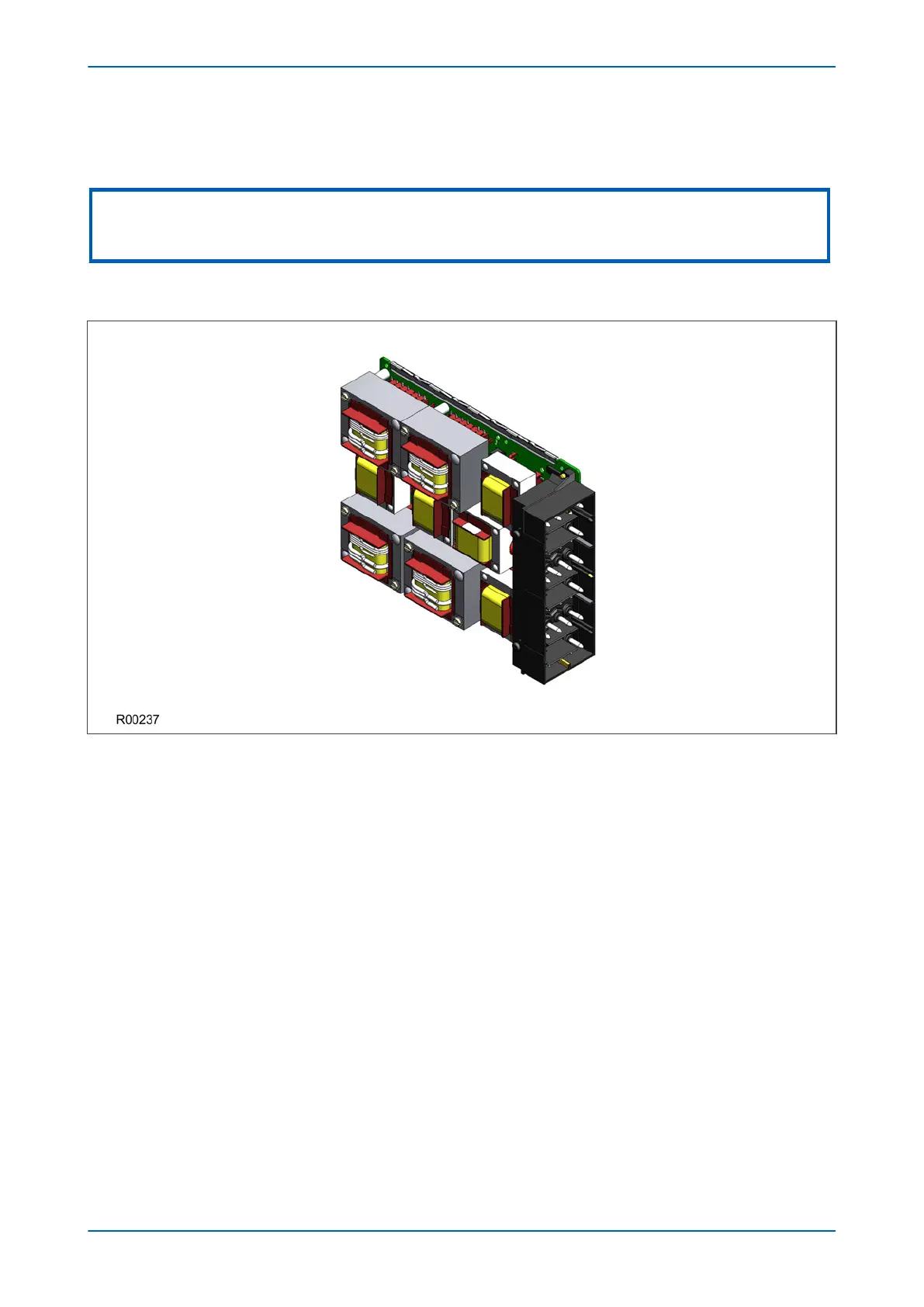
Figure 18: Transformer board
The transformer boar
d hosts the current and voltage transformers. These are used to step down the currents and
voltages originating from the power systems' current and voltage transformers to levels that can be used by the
devices' electronic circuitry. In addition to this, the on-board CT and VT transformers provide electrical isolation
between the unit and the power system.
The transformer board is connected physically and electrically to the input board to form a complete input module.
For terminal connections, please refer to the wiring diagrams.
P54A/B/C/E Chapter 3 - Hardware Design
P54xMED-TM-EN-1 49