3 CHARGING CURRENT COMPENSATION
For both overhead transmission lines and underground cables, there are significant capacitive currents from
gr
ound to the conductor due to the equivalent shunt admittance between the line and the ground. If this current is
not compensated, the differential current will possibly be higher than the Ibias when there is no fault or even when
external fault occurs. Therefore, in order to increase the reliability, sensitivity and security of the differential
protection, the capacitive current of the transmission lines should be eliminated, especially for the lines that are
longer than 50km, or for cables longer than 10km.
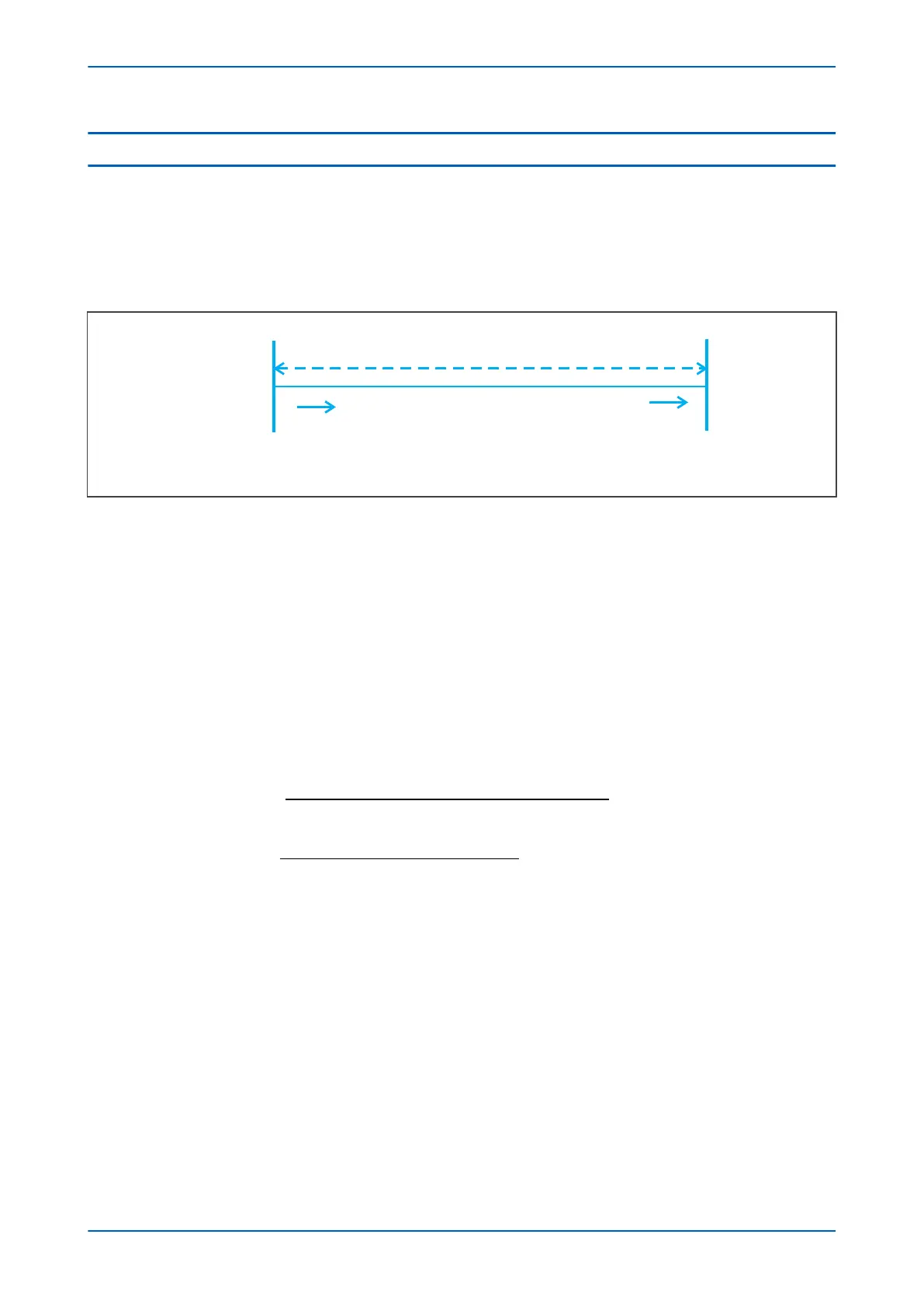
Figure 35: Two-ended transmission line
For example, considering a 2-ended transmission line, the objectiv
e for the capacitive current calculation is to
calculate the current at terminal N based on the voltage and current at terminal M.
Single-phase line algorithm
The mathematical model for calculating the charging current of a transmission line or cable is based on a
distributed parameter line model. From the testing, the distributed parameter line model is proven to be more
accurate than the lumped model. This model is good especially for longer lines. In order to be adaptive to all
transient components as much as possible and to avoid the Fourier computation, the sample based algorithm is
employed, which is inverse transform from the equation in frequency domain. For example, a single-phase line
with terminal M and N, the relationship between the voltage and current at two ends in time domain is shown in
the following equation:
N
P C
p
M
p C
M
C p
N P C
p
M
V
T T
K
f
T T
b
T K
I T T
K
f
t
t t
t
t
( )
( ) ( )/
( )
(
− − =
− − + −
− − =
−
2
2
22
2
p
M
p
CM
T
b
K
Z
t) ( )/+
where:
F
M
is for
ward travelling wave on terminal M in frequency domain;
B
M
is backward travelling wave on terminal M in frequency domain;
V
M
and I
M
are the voltage and current at terminal M in frequency domain;
V
N
and I
N
are the voltage and current at terminal N in frequency domain;
Z
CM
is the absolute value of Z
C
defined above;
T
c
is the time delay made by the phase of Z
C defined above;
Chapter 6 - Current Differential Protection P54A/B/C/E
104 P54xMED-TM-EN-1