5.2 CIRCUIT BREAKER OPEN LOGIC
The Circuit Breaker Open logic module produces internal signals indicating the open status of one or more phases.
These signals ar
e used by some of the Autoreclose logic modules.
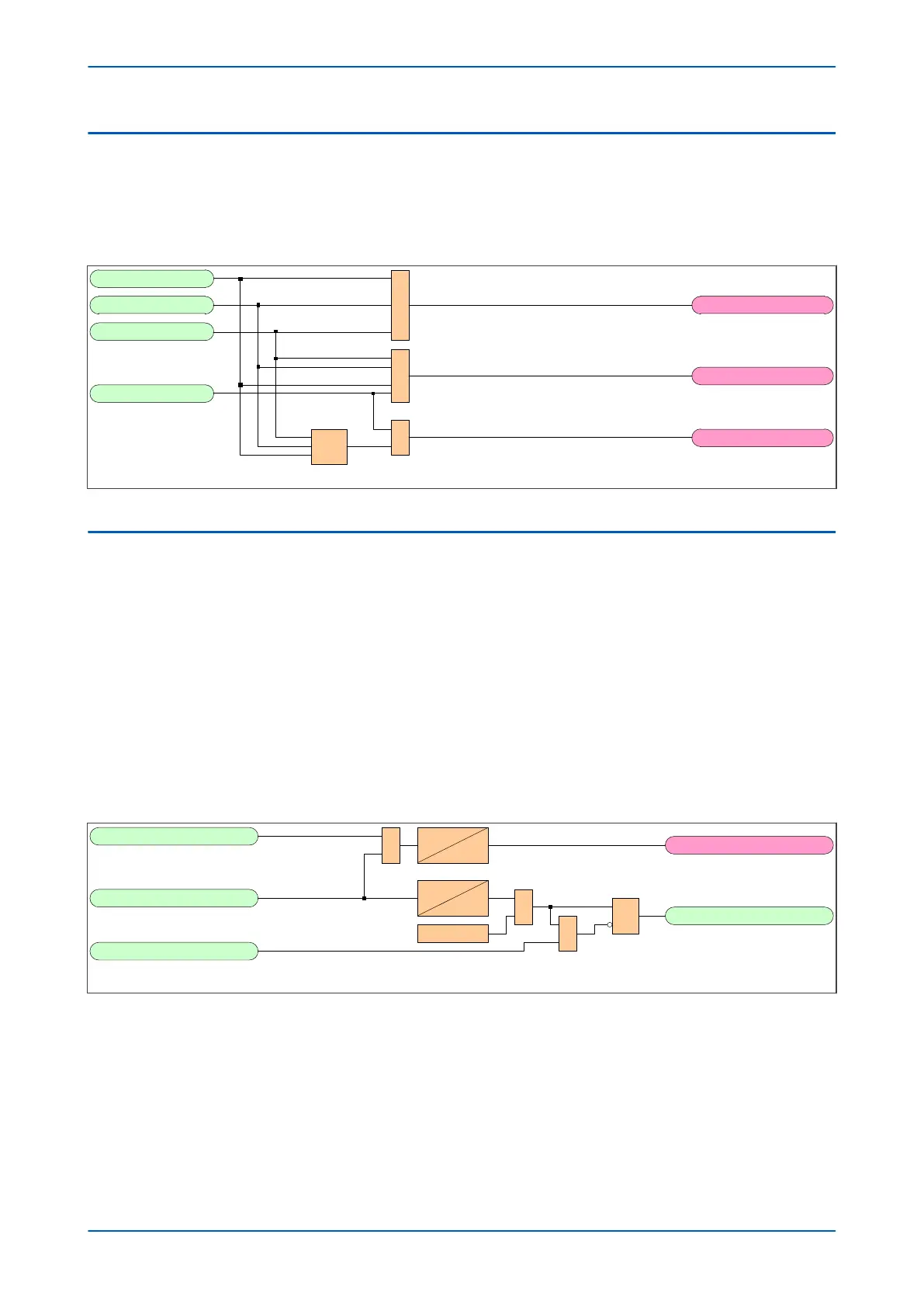
5.2.1 CIRCUIT BREAKER OPEN LOGIC DIAGRAM
V03389
CB Open 3 ph
CB Open B ph
CB Open C ph
CB Open A ph
1
1
CB1Op1P
CB1OpAny
CB1Op2/3P1
³2
Figure 58: Circuit Breaker Open logic diagram (Module 3)
5.3 CIRCUIT BREAKER IN SERVICE LOGIC
For Autoreclose to proceed, a circuit breaker has to be in service when the Autoreclose is initiated. A circuit breaker
is consider
ed to be in service if it has been closed for more than the CB IS Time setting.
For applications with fast-acting circuit breaker auxiliary switches, a time delay setting CB IS Memory Time is
provided. This is used to ensure correct operation if a delay between the circuit breaker tripping and recognition by
the protection, is expected.
When an Autoreclose cycle starts, the “in service” signal for a circuit breaker stays set until the Autoreclose cycle
finishes.
The circuit breaker “in service” signal resets if the circuit breaker opens, or if the corresponding Autoreclose in
progress (ARIP) signal resets.
5.3.1 CIRCUIT BREAKER IN SERVICE LOGIC DIAGRAM
A/R Lockout
&
CB Closed 3 ph
CB1CRLO
V03302
CBIST
0
CBIST
CBISMT
&
R
Q
S
1
CB In Service
Logic 1
CB ARIP
Figure 59: CB In Service logic diagram (Module 4)
P54A/B/C/E Chapter 7 - Autoreclose
P54xMED-TM-EN-1 149