IM64 Ch2 output 8
IM64 Ch1 output 8
Aided 1 COS/LGS
1
&
V02505
Opto 1
Control Input 1
Test Loopback
Test IM64
Signalling Fail
IM64 Ch1 Input 8
IM64 Ch2 Input 8
1
LED 8
Non-
Latching
These inputs are user controls that indicate
when the signalling is locally switched out of
service
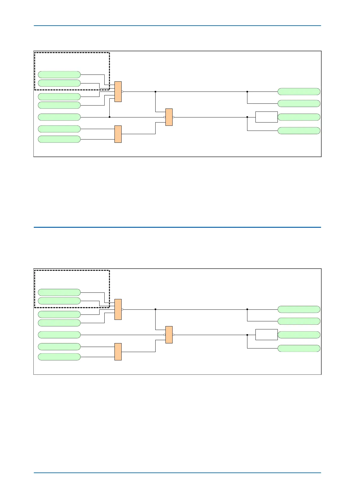
Figure 164: IM64 two-terminal scheme extended supervision
In this example scheme, several signals are used to permanently pass an IM64 signal to the remote terminal.
These signals take account of the local ability to receive IM64 messages, local test/loopback modes and any other
external methods of switching the signalling scheme out of service. If any of these driving signals are energised,
the IM64 message is reset (a “0” sent on IM64 bit 8). This causes both ends to raise an alarm (LED 8 in the example)
or switch the aided scheme out of service due to loss of channel.
This is intended only as an example. You may need to customise it for your application requirements.
5.5 THREE-ENDED SCHEME EXTENDED SUPERVISION
The example for an IM64 two-terminal scheme above can be used for three-terminal applications. However for
thr
ee-terminal applications, the IM64 SchemeFail signal that is automatically communicated to all ends of the
scheme is used rather than the Signalling Fail signal.
IM64 Ch2 output 8
IM64 Ch1 output 8
Aided 1 COS/LGS
1
&
V02506
Opto 1
Control Input 1
Test Loopback
Test IM64
Signalling Fail
IM64 Ch1 Input 8
IM64 Ch2 Input 8
1
LED 8
Non-
Latching
These inputs are user controls
that indicate when the signalling
is locally switched out of service
Figure 165: IM64 three-terminal scheme extended supervision
In this example if both channels at any one terminal fail to r
eceive information, this is communicated to the other
terminals. An alarm is raised and the aided scheme is switched out of service. The example given above, also takes
into account the test modes and local switching, so the scheme is signalled out of service at all terminals if one
terminal is locally disabled.
The logic presented above is intended only as an example. You may need to customise it for your application
requirements.
P54A/B/C/E Chapter 15 - Fibre Teleprotection
P54xMED-TM-EN-1 327