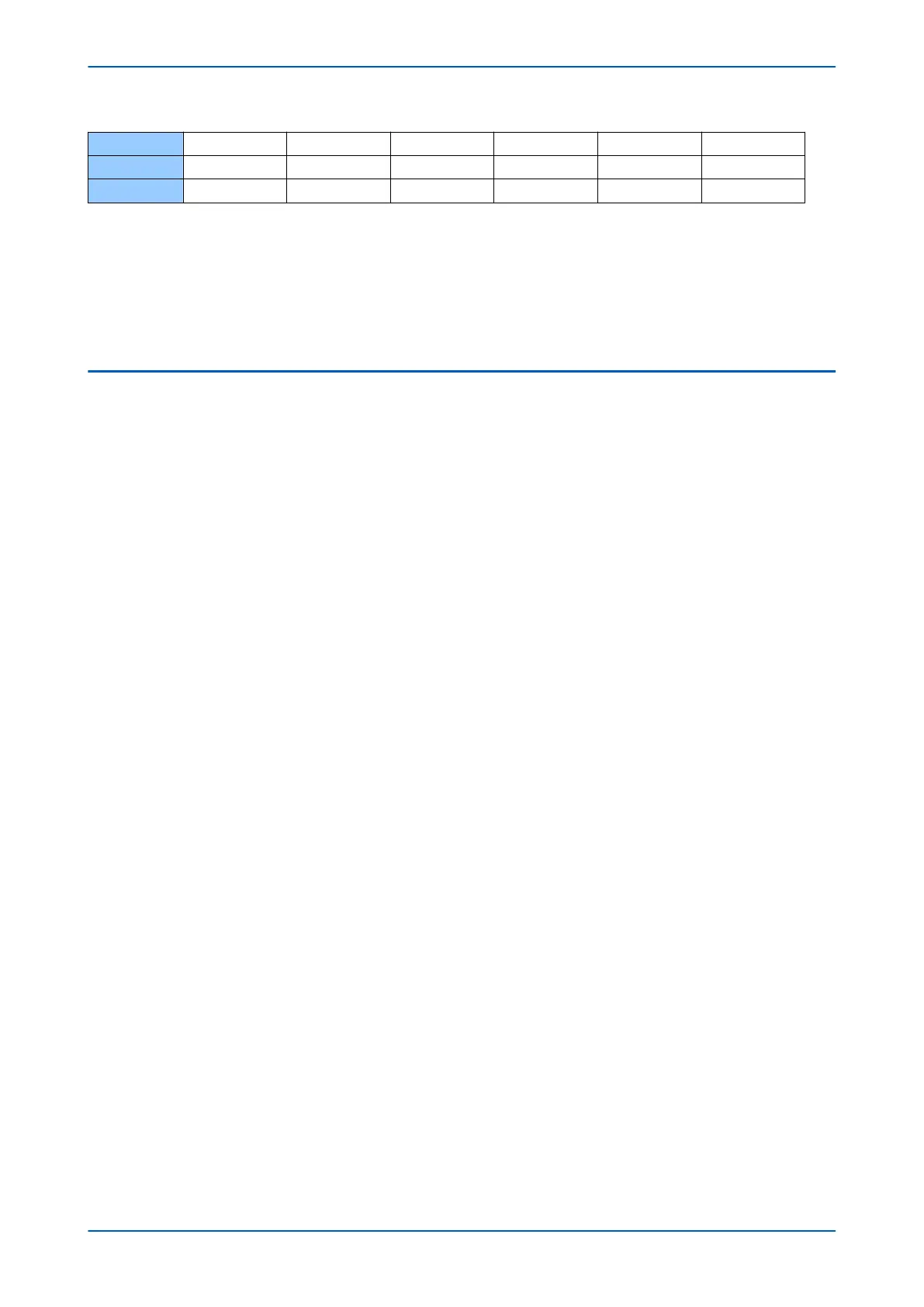
J2 0 0 1 0 0 0
J3 0 0 0 1 0 0
J4 0 0 0 0 1 1
In the example used, each junction is connected to one or two terminals. A '1' is inserted wherever a junction is
connected to a terminal. For example, J1 is connected to both T1 and T2. J2 is connected only to T3. J3 is
connected only to T4. And J4 is connected to both T5 and T6.
The T
opology setting defines the above matrix in a sequence. The first 6 bits represent the terminals connected to
J1, the second 6 bits represent the terminals connected to J2, the third 6 bits represent the terminals connected to
J3 and the fourth 6 bits represent the terminals connected to J4. So the Topology setting would be as follows:
110000001000000100000011
9.4 LINE PARAMETER DATA
The feeder topology is divided up into a number of sections. For the example used, there are 9 sections. This
comprises 6 sections that join the terminals to the near
est junction, and the 3 sections between junctions.
Line length
Each IED must be configured with its local line length, i.e. the length of the line from where the IED is situated to the
nearest junction. In addition each IED must be configured with the line length between junctions. This is achieved
with the following settings:
● Length Local
● Length J1-J2
● Length J2-J3
● Length J3-J4
The line length for each section is specified in km or miles.
Line impedance and admittance
In order to set the admittance and/or impedance values, we need to consider the type of line. There are essentially
two types of power line; Overhead (uninsulated) or underground (insulated). Line type selection is achieved using
the following settings:
● Line Type Local
● Line Type J1-J2
● Line Type J2-J3
● Line Type J3-J4
Overhead lines have very low shunt capacitance of a value that is fairly consistent and well known. This is taken
into consideration when the device makes its calculations and need not be further considered. All you need to do is
enter the per kilometer series inductive line impedance for the transmission line.
Underground cables have much higher shunt capacitance than overhead lines. The per kilometer shunt
capacitance is dependent on the type of cable, and is usually a separate specification supplied by the cable
manufacturer. Underground cables will therefore have two specifications supplied; series inductive impedance and
shunt capacitive admittance. You will need to enter both parameters for underground cables.
Each IED must be configured with the positive sequence impedance amplitude and angle of the local section
length and the sections between the junctions, and similar parameters for zero sequence impedance and positive
sequence admittance. All relevant settings are shown below:
Z1Local Positive sequence impedance amplitude of the local section length per KM
Z1LocalAngle Positive Sequence impedance angle of the local section length
P54A/B/C/E Chapter 6 - Current Differential Protection
P54xMED-TM-EN-1 117