9.2 FEEDER TOPOLOGY
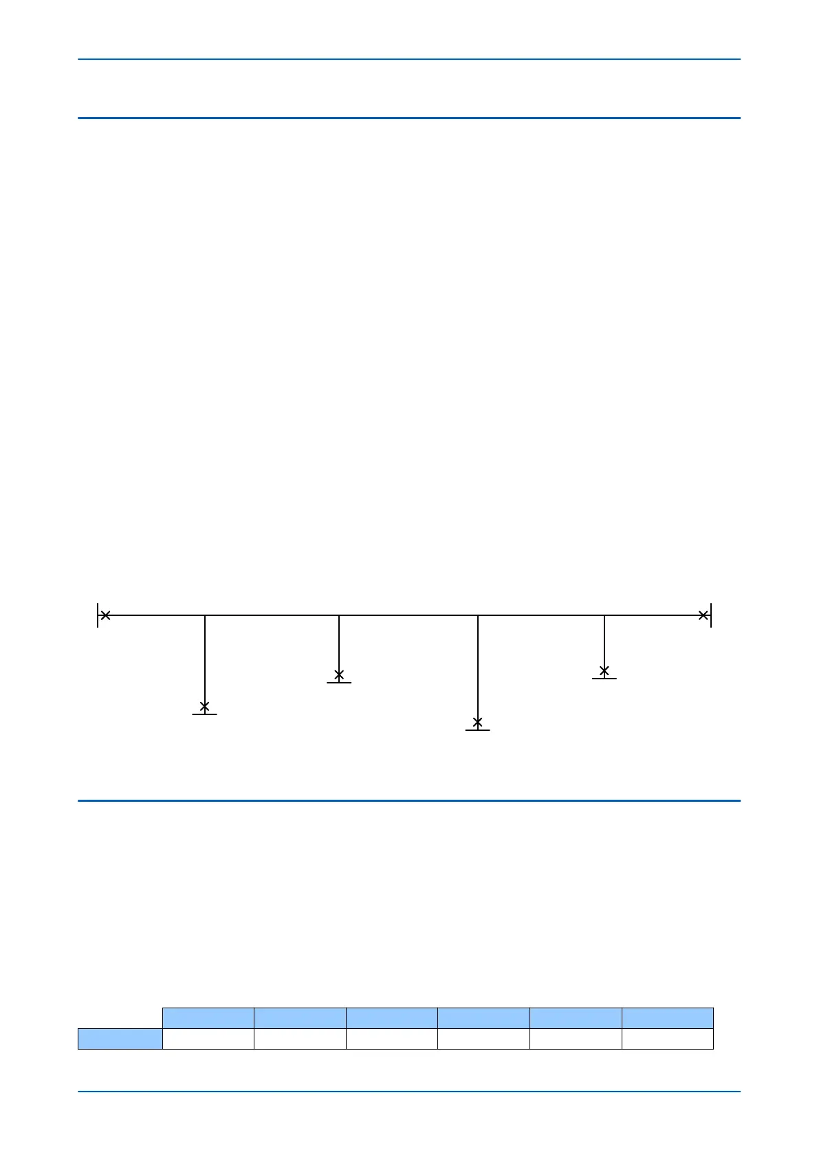
A single-line diagram is used to describe the feeder topology. The diagram below identifies terminals and
Junctions. A terminal (T) r
epresents an external connection point to the protected feeder. A junction (J) represents a
connection point, which is internal to the protection scheme. A junction connects terminals together, either directly
or indirectly (via another Junction).
The terminals are numbered as T1, T2, T3 etc. So in a 6-terminal scheme, the terminals are numbered T1, T2, T3, T4,
T5 and T6. The allocation of terminal numbers is arbitrary, but to save confusion, we recommend adopting a “left-
to-right” convention starting with T1.
The IEDs used at each terminal must be defined with A, B, C etc. So in a 6-terminal scheme, the IEDs are defined as
A, B, C, D, E and F. Each IED in the scheme must have a different name. Although the terminal numbers do not have
to correspond to the IED names in sequence, it is better to do this as a convention, as this may save confusion. So
we recommend naming the IEDs as follows:
● A at T1
● B at T2
● C at T3
● D at T4
● E at T5
● F at T6
The junctions are numbered from sequentially starting from J1. In a 6-terminal scheme, the junctions are
numbered J1, J2, J3 and J4. The allocation of junction numbers is critical to the protection scheme and the
numbering must be rigidly adhered to. You can start at either the left-hand junction or the right-hand junction, but
the first one chosen must be J1 with the next adjacent junctions J2, J3, and J4 in sequence as appropriate. To save
confusion, we recommend adopting the “left-to-right” convention as shown in the diagram, below.
V02624
T1
T2
T3
T4
T5
T6
J1 J2 J3 J4
Line length: LJ1J2 Line length: LJ2J3 Line length: LJ3J4
Line length: LLocal
Line length: LLocalLine length: LLocal
Line length: LLocal
Line length: LLocal
Line length: LLocal
IED A
IED B
IED C
IED D
IED E
IED F
Figure 47: Six terminal, four junction topology
9.3 CONFIGURING THE FEEDER TOPOLOGY
When you have defined the scheme topology, you need to programme it into each device in the scheme.
For each device y
ou need to programme the number of terminals, the number of junctions, and a topology
connection matrix. You do this using the settings, No. of Terminals and No. of Junctions in the PROT COMMS/IM64
column and the Topology setting in the LINE PARAMETERS column.
No. of Terminals defines the number of terminals in the scheme, which can be from 2 to 6.
No. of Junctions defines the number of junctions in the scheme, which can be from 1 to 4
The Topology setting is a 24-bit binary string, which defines the topology connection matrix in a sequence. To
demonstrate how this is applied, consider the following topology arrangement:
T1 T2 T3 T4 T5 T6
J1 1 1 0 0 0 0
Chapter 6 - Current Differential Protection P54A/B/C/E
116 P54xMED-TM-EN-1