t
op
is the operating time
I is the measur
ed current
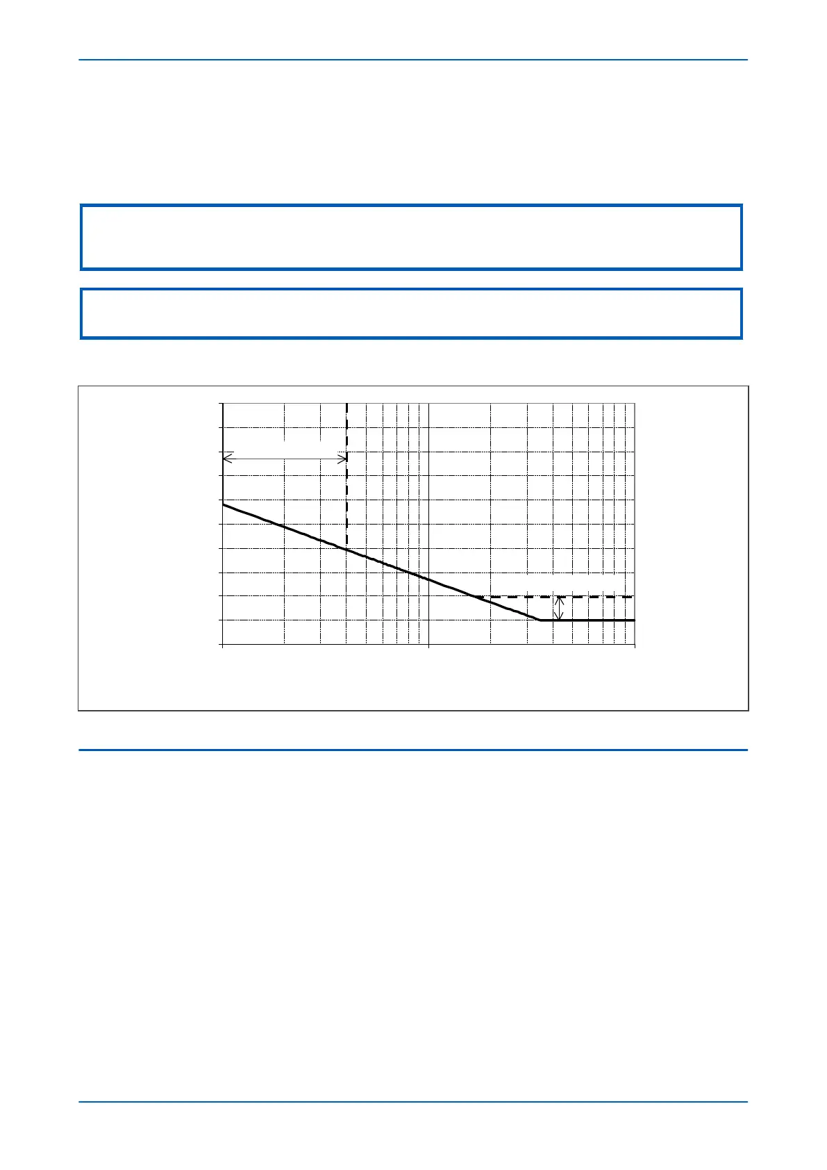
IN> Setting is an adjustable setting, which defines the start point of the characteristic
Note:
Although the start point of the characteristic is defined by the "ΙN>" setting, the actual current threshold is a different setting
called "IDG Ιs". The "IDG Ιs" setting is set as a multiple of "ΙN>".
Note:
When using an IDG Operat
e characteristic, DT is always used with a value of zero for the Rest characteristic.
An additional setting "IDG Time" is also used to set the minimum operating time at high levels of fault current.
V00611
IDG Time Setting Range
IDG Is Setting Range
O
p
e
r
a
t
i
n
g
t
i
m
e
(
s
e
c
o
n
d
s
)
Figure 100: IDG Characteristic
4.3 DIRECTIONAL ELEMENT
If Earth fault current can flow in both directions through a protected location, you will need to use a directional
ov
ercurrent element to determine the direction of the fault. Typical systems that require such protection are
parallel feeders and ring main systems.
A directional element is available for all of the Earth Fault stages. These are found in the direction setting cells for
the relevant stage. They can be set to non-directional, directional forward, or directional reverse.
Directional control can be blocked by the VTS element if required.
For standard earth fault protection, two options are available for polarisation; Residual Voltage (zero sequence) or
Negative Sequence.
4.3.1 RESIDUAL VOLTAGE POLARISATION
With earth fault protection, the polarising signal needs to be representative of the earth fault condition. As residual
v
oltage is generated during earth fault conditions, this quantity is commonly used to polarise directional earth
fault elements. This is known as Zero Sequence Voltage polarisation, Residual Voltage polarisation or Neutral
Displacement Voltage (NVD) polarisation.
P54A/B/C/E Chapter 9 - Current Protection Functions
P54xMED-TM-EN-1 203