P54A/B/C/E
Appendix A - Ordering Options
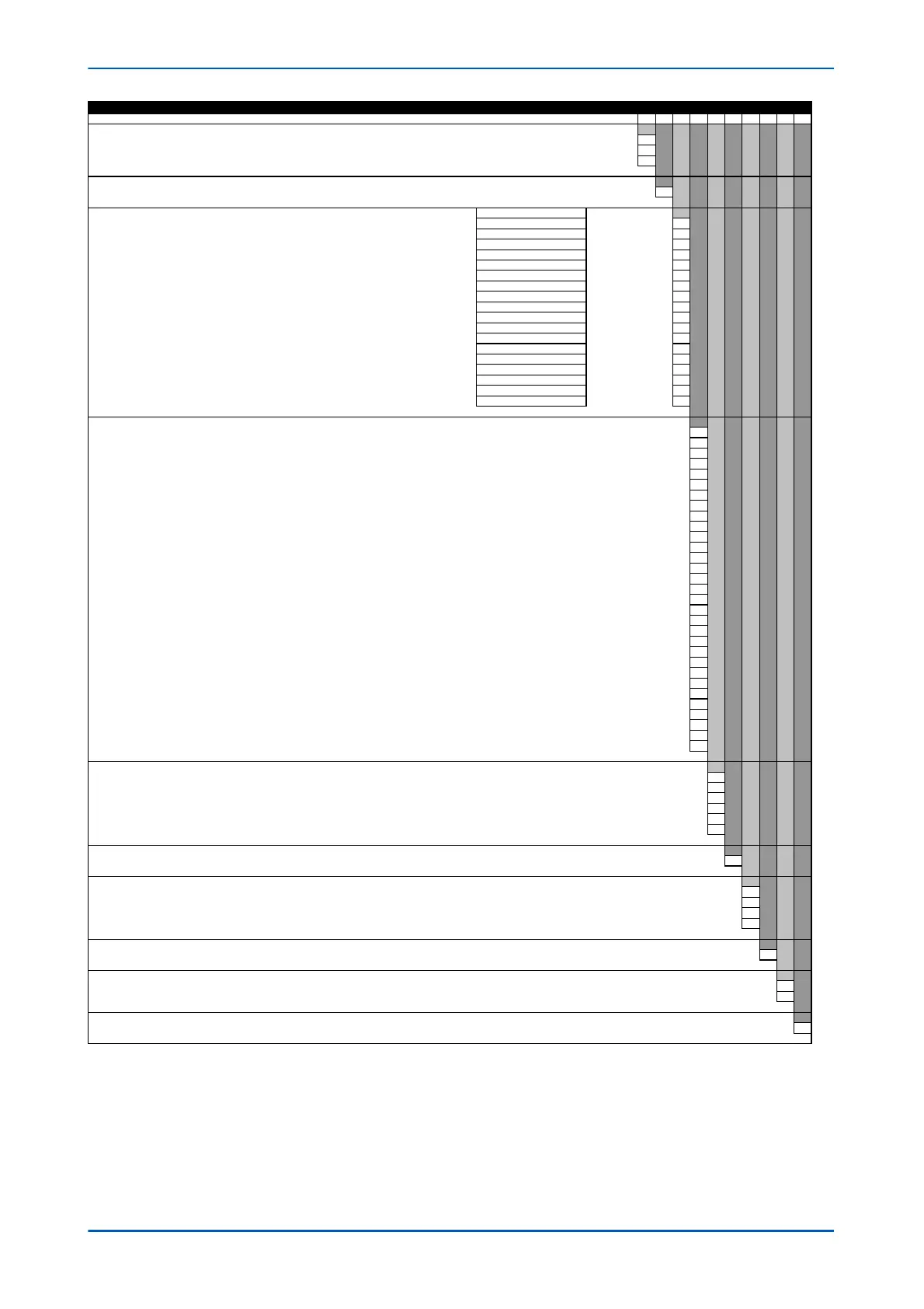
Order No.
ariants
Current differential - 60TE with 1/3
ole autoreclose and check s
nchronisin
u
to 6 ends a
lication
P54C
**
Nominal auxiliar
volta
e
24-54 Vdc
7
48-125 Vdc
40-100 Vac
8
110-250 Vdc
100-240 Vac
9
In/Vn ratin
In = 1A/5A ; Vn = 100-120Vac
1
Hardware o
tions
Protocol Com
atibilt
Standard - None
1, 3 & 4 1
IRIG-B Onl
Modulated
1, 3 & 4 2
Fibre O
tic Converter Onl
1, 3 & 4 3
IRIG-B
Modulated
& Fibre O
tic Converter
1, 3 & 4 4
Ethernet
100Mbit/s
1, 3 & 4 6
Ethernet
100Mbit/s
lus IRIG-B
Modulated
6, 7 & 8
Ethernet
100Mbit/s
lus IRIG-B
Un-modulated
6, 7 & 8 B
IRIG-B
Un-modulated
1, 3 & 4 C
InterMiCOM + Courier Rear Por
1, 3 & 4 E
InterMiCOM + Courier Rear Port + IRIG-B modulated
1, 3 & 4 F
Redundant Ethernet Self-Healin
Rin
, 2 multi-mode fibre
orts + Modulated IRIG-B
6, 7 & 8 G
Redundant Ethernet Self-Healin
Rin
, 2 multi-mode fibre
orts + Un-modulated IRIG-B
6, 7 & 8 H
Redundant Ethernet RSTP, 2 multi-mode fibre
orts + Modulated IRIG-B
6, 7 & 8 J
Redundant Ethernet RSTP, 2 multi-mode fibre
orts + Un-modulated IRIG-B
6, 7 & 8 K
Redundant Ethernet Dual-Homin
Star, 2 multi-mode fibre
orts + Modulated IRIG-B
6, 7 & 8 L
Redundant Ethernet Dual-Homin
Star, 2 multi-mode fibre
orts + Un-modulated IRIG-B
6, 7 & 8 M
Redundant Ethernet PRP/HSR, 2 fibre
orts + Modulated IRIG-B 6, 7 & 8 N
Redundant Ethernet PRP/HSR, 2 fibre
orts + Unmodulated IRIG-B 6, 7 & 8 P
Product O
tions
Ch1=850nm multi-mode, Ch2=850nm multi-mode, 16 In
uts and 16 Out
ut Rela
s
Ch1=1300nm sin
le-mode, Ch2=not fitted
2 Terminal onl
, 16 In
uts and 16 Out
ut Rela
s
B
Ch1=1300nm sin
le-mode, Ch2=1300nm sin
le-mode, 16 In
uts and 16 Out
ut Rela
s
C
Ch1=1300nm multi-mode, Ch2=not fitted
2 Terminal onl
, 16 In
uts and 16 Out
ut Rela
s
D
Ch1=1300nm multi-mode, Ch2=1300nm multi-mode, 16 In
uts and 16 Out
ut Rela
s
E
Ch1=1550nm sin
le-mode, Ch2=not fitted
2 Terminal onl
, 16 In
uts and 16 Out
ut Rela
s
F
Ch1=1550nm sin
le-mode, Ch2=1550nm sin
le-mode, 16 In
uts and 16 Out
ut Rela
s
G
Ch1=850nm multi-mode, Ch2=1300nm sin
le-mode, 16 In
uts and 16 Out
ut Rela
s
H
Ch1=850nm multi-mode, Ch2=1300nm multi-mode, 16 In
uts and 16 Out
ut Rela
s
J
Ch1=850nm multi-mode, Ch2=1550nm sin
le-mode, 16 In
uts and 16 Out
ut Rela
s
K
Ch1=1300nm sin
le-mode, Ch2=850nm multi-mode, 16 In
uts and 16 Out
ut Rela
s
L
Ch1=1300nm multi-mode, Ch2=850nm multi-mode, 16 In
uts and 16 Out
ut rela
s
M
Reserved for future sin
le channel
N
Reserved for future sin
le channel
P
Ch1 1550nm sin
le-mode, Ch2 850nm multi-mode, 16 In
uts and 16 Out
ut Rela
s
R
Ch1=850nm multi-mode, Ch2=850nm multi-mode, 16 In
uts and 12 Out
uts Rela
s
Includin
4 Hi
h Break
S
Ch1=1300nm sin
le-mode, Ch2=not fitted
2 Terminal onl
, 16 In
uts and 12 Out
ut rela
s
Includin
4 Hi
h Break
T
Ch1=1300nm sin
le-mode , Ch2=1300nm sin
le-mode, 16 In
uts and 12 Out
uts
Includin
4 Hi
h Break
U
Ch1=1300nm multi-mode, Ch2=not fitted
2 Terminal onl
, 16 In
uts and 12 Out
ut Rela
s
Includin
4 Hi
h Break
Ch1=1300nm multi-mode, Ch2=1300nm multi-mode, 16 In
uts and 12 Out
uts
Includin
4 Hi
h Break
Ch1=1550nm sin
le-mode, Ch2=not fitted
2 Terminal onl
, 16 In
uts and 12 Out
ut Rela
s
includin
4 Hi
h Break
X
Reserved - was used for RWE s
ecial
Ch1=1550nm sin
le-mode, Ch2=1550nm sin
le-mode, 16 In
uts and 12 Out
ut Rela
s
Includin
4 Hi
h Break
Z
Ch1=850nm multi-mode, Ch2=1300nm sin
le-mode, 16 In
uts and 12 Out
uts
Includin
4 Hi
h Break
0
Ch1=850nm multi-mode, Ch2=1300nm multi-mode, 16 In
uts and 12 Out
uts
Includin
4 Hi
h Break
1
Ch1=850nm multi-mode, Ch2=1550nm sin
le-mode, 16 In
uts and 12 Out
ut Rela
s
Includin
4 Hi
h Break
2
Ch1=1300nm sin
le-mode, Ch2=850nm multi-mode, 16 In
uts and 12 Out
ut Rela
s
Includin
4 Hi
h Break
3
Ch1=1300nm multi-mode, Ch2=850nm multi-mode, 16 In
uts and 12 Out
ut Rela
s
Includin
4 Hi
h Break
4
Ch1=1550nm sin
le-mode, Ch2=850nm multi-mode, 16 In
uts and 12 Out
ut Rela
s
Includin
4 Hi
h Break
5
Reserved for future sin
le channel
6
Reserved for future sin
le channel
7
Protocol o
tions
K-Bus
1
IEC60870-5-103
VDEW
3
DNP3.0
4
IEC61850 + Courier via rear RS485
ort
6
IEC61850 + IEC60870-5-103 via rear RS485
ort
7
DNP3.0 Over Ethernet with Courier rear
ort K-Bus/RS485
rotocol 8
Mountin
Flush/Panel Mountin
with Harsh Environment Coatin
M
Lan
ua
e
En
lish, French, German, S
anish
0
En
lish, French, German, Russian
5
En
lish, Italian, Polish and Portu
uese
7
Chinese, En
lish or French via HMI, with En
lish or French onl
via Communications
ort
C
Software version
Without Distance
01
Customer s
ecific o
tions
Standard version
0
Customer version
Hardware version
XCPU3 with increased main
rocessor memor
M
P54xMED-TM-EN-1
A3