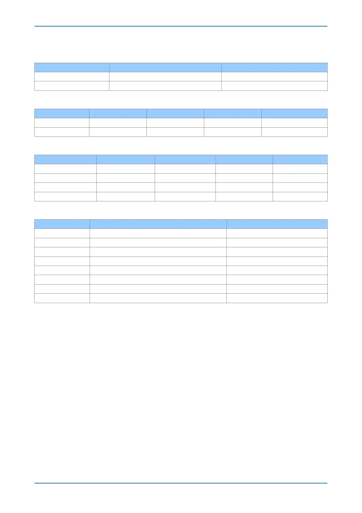
Link Fail Connector (Ethernet Board Watchdog Relay)
Pin Closed Open
1-2 Link fail Channel 1 (A) Link ok Channel 1 (A)
2-3 Link fail Channel 2 (B) Link ok Channel 2 (B)
LEDs
LED Function On Off Flashing
Green Link Link ok Link broken
Yellow Activity SHP running PRP, RSTP or DHP traffic
Optical Fibre Connectors (ST)
Connector DHP RSTP SHP PRP
A RXA RX1 RS RXA
B TXA TX1 ES TXA
C RXB RX2 RP RXB
D TXB TX2 EP TXB
RJ45connector
Pin Signal name Signal definition
1 TXP Transmit (positive)
2 TXN Transmit (negative)
3 RXP Receive (positive)
4 - Not used
5 - Not used
6 RXN Receive (negative)
7 - Not used
8 - Not used
P54A/B/C/E Chapter 3 - Hardware Design
P54xMED-TM-EN-1 57