PART 4
ENGINE/DC CONTROL
Page 116
Section 4.5
Diagnostic Tests
TEST 41 – TRY A MANUAL START
Discussion
The first step in troubleshooting for an “engine won’t crank”
condition is to determine if the problem is related to automatic
operations only or if the engine will not crank manually either.
Procedure
1. Set the AUTO-OFF-MANUAL switch to the OFF position.
2. Set the main line circuit breaker (MLCB) to the “Open”
position.
3. Set the AUTO-OFF-MANUAL switch to the MANUAL
position.
a. The engine should crank cyclically through its “crank-
rest” cycles until it starts.
b. Let the engine stabilize and warm up for a few minutes
after it starts.
Results
1. If the engine cranks manually, but does not crank
automatically, refer back to flow chart.
2. If the engine does not crank manually proceed to Problem
15.
TEST 42 – TEST THE AUTO-OFF-MANUAL
SWITCH
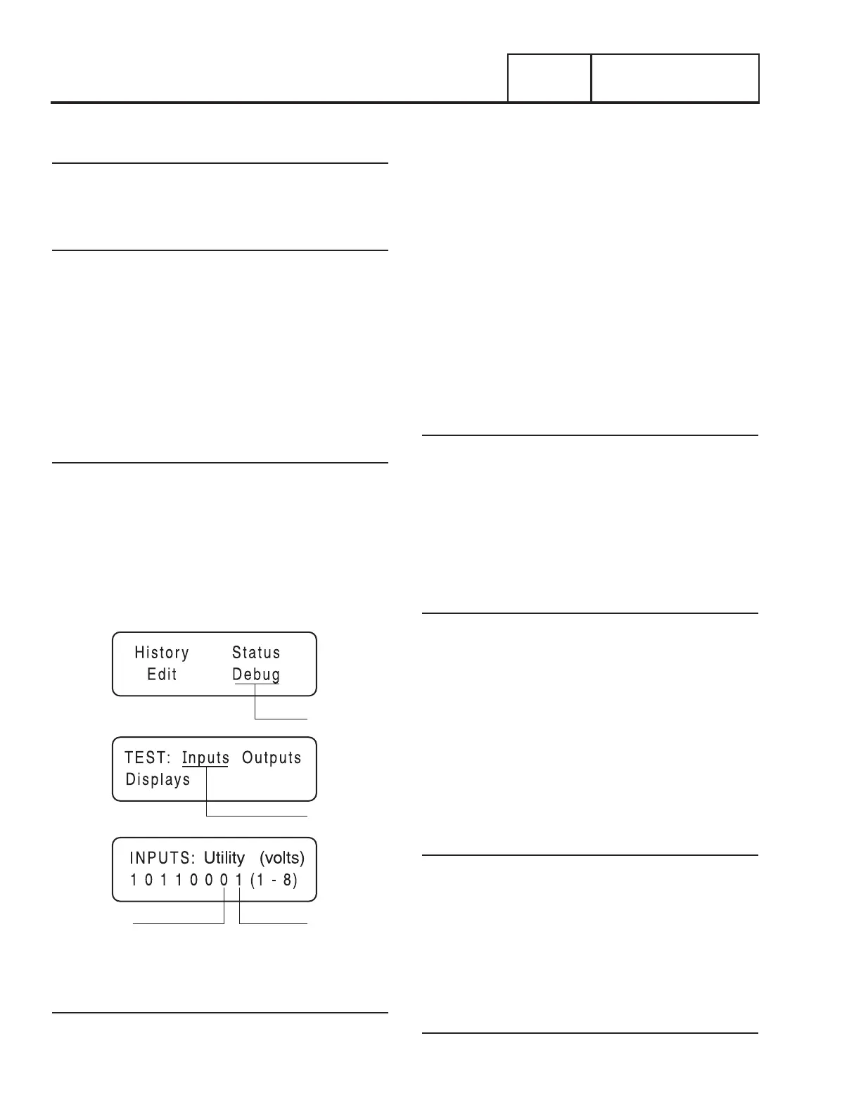
INPUT 7 INPUT 8
DEBUG
1
2
3
INPUTS
Figure 108. The Home Page, Debug and Input Screens
Procedure
1. Press the “ESC” key on the controller until the home page
is reached (Figure 108, Screen 1).
2. Press the right arrow key until “Debug” flashes. Press
“Enter” and the following screen will appear. See Figure
108, Screen 2.
3. When “Inputs” flashes, press “Enter”.
4. With the Inputs Screen displayed, place the AUTO-OFF-
MANUAL switch to the AUTO Position. If the controller
reads the auto input from the switch, Input 7 will change
from “0” to “1”. See Table 17 in Section 4.1 for a
description of the Inputs.
5. With the Inputs Screen displayed place the AUTO-OFF-
MANUAL switch to the MANUAL position. If the controller
reads an input from the Switch, Input 8 will change from
“0” to “1”.
6. With the AUTO-OFF-MANUAL Switch in the OFF position,
both inputs will read zero.
Results
1. If controller failed either Step 4 or Step 5, replace the
controller assembly.
2. If the controller passed Step 4 and Step 5, refer back to
flow chart.
TEST 43 – TEST AUTO OPERATIONS OF
CONTROLLER
Discussion
Initial Conditions: The Generator is in AUTO, ready to run, and
voltage is being supplied by Utility. When Utility fails (below
65% of nominal), a 10 second (optionally programmable) line
interrupt delay time is started. If the Utility is still gone when the
timer expires, the engine will crank and start. Once started a
five (5) second “engine warm-up timer” will be initiated. When
the warm-up timer expires, the controller will transfer the load
to the Generator. If Utility voltage is restored (above 75% of
nominal) at any time from the initiation of the engine start until
the Generator is ready to accept a load (5 second warm-up time
has not elapsed), the controller will complete the start cycle
and run the Generator through its normal cool down cycle;
however, the voltage will remain on the Utility source.
Procedure
1. Place the generator Auto-Off-Manual switch in the Auto
position.
2. Simulate a power failure by opening Utility supply breaker.
If the generator cranks and starts and the switch transfers,
the test is good; STOP.
3. If the Generator does not perform the sequence of events
listed in the above discussion, replace the controller.
Results
Refer back to the flow chart

 Loading...


