PART 1
GENERAL INFORMATION
Page 14
Section 1.2
Installation Basics
vary considerably, depending on ambient temperatures. In
cold weather, supply pressures may drop to “zero”. In warm
weather, extremely high gas pressures may be encountered.
A primary regulator is required to maintain correct gas supply
pressures.
Required fuel pressure for natural gas is 5 inches to 7 inches
water column (0.18 to 0.25 psi); and for liquid propane, 10
inches to 12 inches of water column (0.36 to 0.43 psi).
Note: To maintain proper fuel pressure a primary regulator
is required.
LP and Natural Gas are both highly explosive. Gaseous
fuel lines must be properly purged and tested for
leaks before this equipment is placed into service and
periodically thereafter. Procedures used in gaseous
fuel leakage tests must comply strictly with applicable
fuel gas codes. Do not use flame or any source of heat
to test for gas leaks. No gas leakage is permitted. LP
gas is heavier than air and tends to settle in low areas.
Natural gas is lighter than air and tends to settle in high
places. Even the slightest spark can ignite these fuels
and cause an explosion.
Use a flexible length of hose between the Generator fuel
connection and rigid fuel lines is required. This will help
prevent line breakage that might be caused by vibration or if
the Generator shifts or settles. The flexible fuel line must be
approved for use with gaseous fuels.
Flexible fuel line should be kept as straight as possible between
connections. The bend radius for flexible fuel lines is nine (9)
inches. Exceeding the bend radius can cause the fittings to
crack.
TRANSFER SWITCH / LOAD CENTER
Electrical code requires the use of a transfer switch, to prevent
electrical feedback between the Utility and Standby power
sources, and to transfer electrical loads from one power supply
to another safely. See Section 3.1 for further information.
POWER SOURCE AND LOAD LINES
The Utility supply lines, the Standby supply lines, and electrical
Load lines must all be connected to the proper terminal lugs in
the transfer switch. In single phase systems only with a 2-pole
CONTACTOR the following installation procedure applies.
Connect the two Utility source (hot) lines to the CONTACTOR
terminal lugs labeled N1 and N2. Connect the Standby source
(hot) lines to the CONTACTOR terminal lugs labeled E1 and E2.
Connect the Load lines to the CONTACTOR terminal lugs labeled
T1 and T2. Connect the Utility, Standby, and Load Neutral lines
to the NEUTRAL block in the transfer switch.
0000001
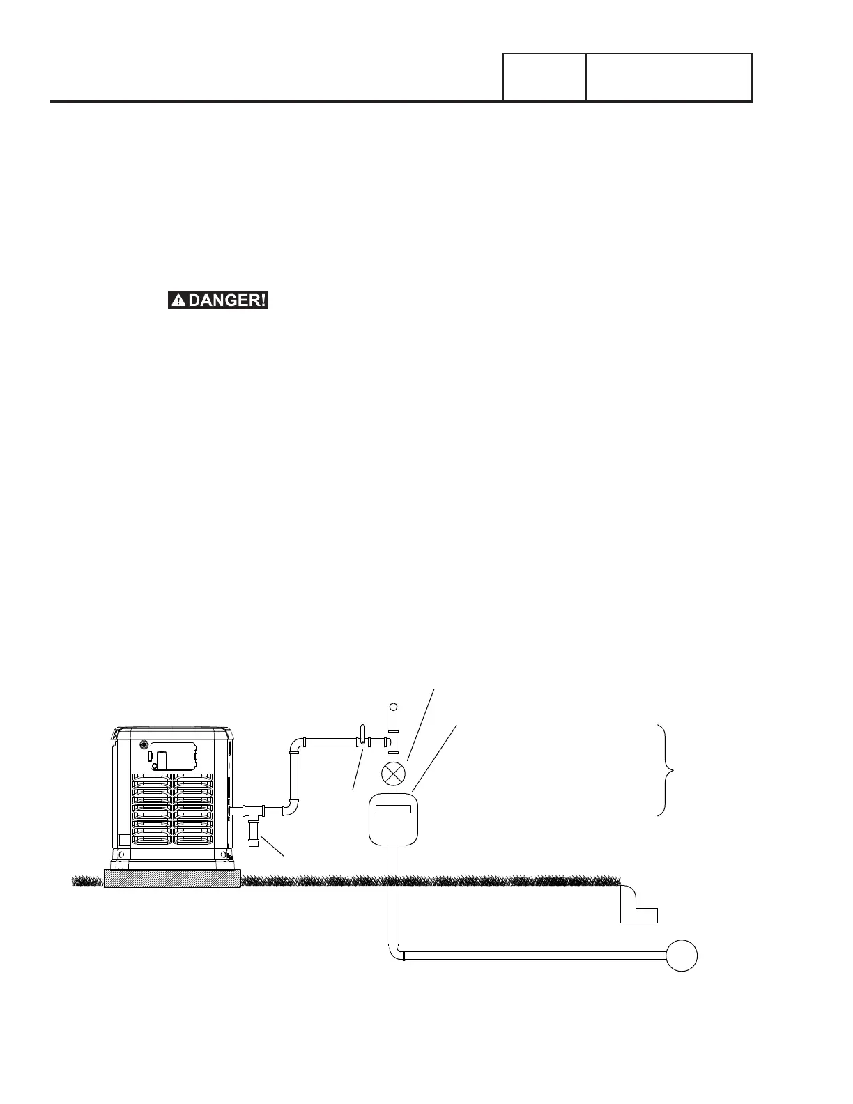
GAS MAIN
2-5 PSI
5-7” WC REGULATOR
TO HOUSEHOLD
GAS METER CAPABLE
+HOUSEHOLD APPLIANCES
FUEL FLOW OF:
OF PROVIDING NATURAL GAS
SAFETY
SHUT OFF
VALVE
TRAP
(BASED ON 1000 BTU/CU FT)
BTU/HOUR
140,000 (7 kW)
156,000 (9 kW)
215,000 (12 kW)
220,000 (13 kW)
245,000 (15kW)
261,000 (16 kW)
294,000 (18 kW)
Figure 8. Proper Fuel Installation
NATURAL GAS FUEL INTERCONNECTIONS

 Loading...


