PART 4
ENGINE/DC CONTROL
Page 92
Section 4.1
Description and Components
16
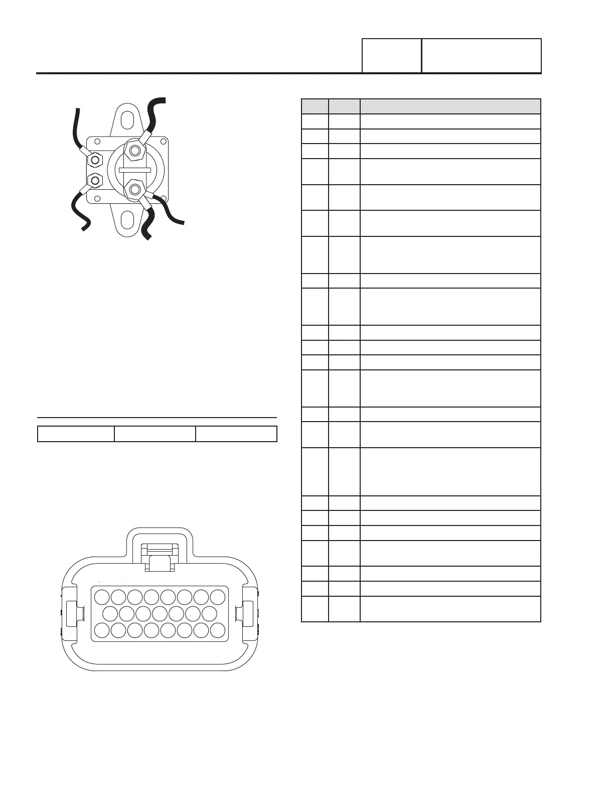
TO STARTER
13
TO BATTERY
13
TO CONTROLLER
CONNECTOR J4 - PIN 3
0
TO GROUND
56
TO CONTROLLER
Figure 87. The Starter Contactor (Single Cylinder Units)
COMMON ALARM RELAY
The common alarm relay provides a set of contacts to drive a
customer provided external alarm indication. When the control
is powered up, if there are no Alarms, the relay contacts will
be OPEN. Any ALARM (not warning) will trigger the common
alarm relay to operate, closing the contacts. The connections
are made to the generator customer connection terminal strip
at Terminals 1 and 2 (Wires 209 and 210).
Specifications
Contact Rating: 10A at 250 VAC 5A at 30 VDC
Note: Contact rating is for resistive load only
CONNECTOR PIN DESCRIPTIONS
Figures 88 and 89, and Tables 19 and 20 provide the physical
pin connections as well as the Wire and circuit function.
8
15 14 13 12 11 10 9
23 22 21 20 19 18 17 16
7 6 5 4 3 2 1
Figure 88. J4 Connector (Harness Side)
Table 19. J4 Connector Pin Descriptions
PIN WIRE CIRCUIT FUNCTION
1 90 Switched to ground for choke solenoid operation
2 0 Common Ground (DC)
3 13 12 VDC un-fused for the controller
4 817 Grounded by the controller to turn on System
Ready (Green) LED
5 818 Grounded by the controller to turn on Alarm (Red)
LED
6 819 Grounded by the controller to turn on the
Maintenance (Yellow) LED
7 85 High temperature shutdown: Shutdown occurs
when Wire 85 is grounded by contact closure in
the oil temperature switch
8 820 Positive voltage (5VDC) for status LED's
9 14 12 VDC output for engine run condition. Used
for fuel solenoid and choke solenoid operation on
V-Twin Models
10 210 Common Alarm Relay Output
11 Not used
12 Not used
13 86 Low oil pressure shutdown: Shutdown occurs
when Wire 86 is grounded by loss of oil pressure
in the LOP switch
14 Not used
15 JMP 1 Installed in series with a resistor to identify the kW
to the controller
16 18 Ignition Shutdown: The controller grounds Wire
18 for ignition shutdown and receives a reference
signal for speed control while cranking and
running
17 56 12 VDC output to starter contactor relay/solenoid
18 209 Common Alarm Relay Output
19 194 Provides 12 VDC to the transfer relay (TR1)
20 23 Switched to ground (internally) to energize the
Transfer Relay
21 Not used
22 Not used
23 JMP 1 Installed in series with a resistor to identify the kW
to the controller

 Loading...


