PART 4
ENGINE/DC CONTROL
Page 106
Section 4.3
Operational Analysis
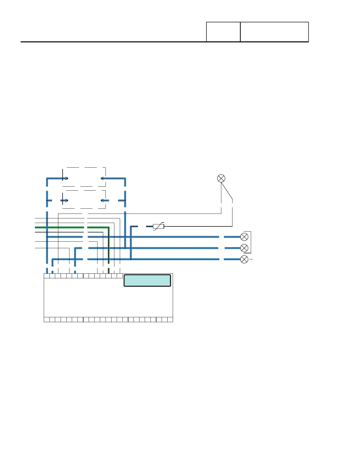
UTILITY VOLTAGE RESTORED AND RE-TRANSFER TO UTILITY
The Load is powered by Generator voltage. On restoration of Utility voltage, the following events will occur:
•On restoration of Utility voltage above 75% of the nominal rated voltage, a “re-transfer time delay” on the controller starts timing.
The timer will run for 15 seconds.
•At the end of the 15 seconds, the “re-transfer time delay” will stop timing. The controller will open the Wire 23 circuit from ground
and the transfer relay (TR1) will de-energize.
•When the TR1 relay de-energizes its utility side contacts close. Utility voltage is then delivered to the utility closing coil (C1), via
Wire N1A and N2A, the closed TR1 contacts, Wire 126, limit switch (SW2), and a bridge rectifier.
•The C1 coil energizes and moves the main contacts to their “Utility” Position; the LOAD terminals are now powered by Utility.
•Movement of the main contacts to the “Utility” position actuates the limit switches. SW2 opens and SW3 moves to the Standby
source side.
•The generator continues to run.
NEUTRAL
INPUT
UTILITY
240 VAC
N1
T1
00 2
N2
44
11
0
4
6
T1
N2
N1
T1
N2
N1
00
6
4
0
11
44
LOAD SUPPLY
120 VAC
WHT00
MOV
T1A
N2AN1A
N2N1
1
2 N2B
N1B
1
CONNECT
240Vac
2
BATTERY WARMER
OPTIONAL
CONNECT
240Vac
OIL WARMER
OPTIONAL
BATTERY CHARGER
J5
PRINTED CIRCUIT BOARD
CONTROLLER
J4
18171615141312109 1186 721 43 5 2322212019
141312109 1186 721 43 5
Running / Cooldown
Figure 103.

 Loading...


