PART 4
ENGINE/DC CONTROL
Page 124
Section 4.5
Diagnostic Tests
3. Disconnect Wire 14 from the fuel solenoid (FS).
4. Connect the positive test lead to the disconnected Wire 14
from Step 3 and connect the negative test lead to a clean
frame ground.
5. Set AUTO-OFF-MANUAL switch to the MANUAL position.
The meter should indicate battery voltage.
a. If battery voltage is indicated, refer back to flow chart.
b. If battery voltage is not measured, proceed to Step 6
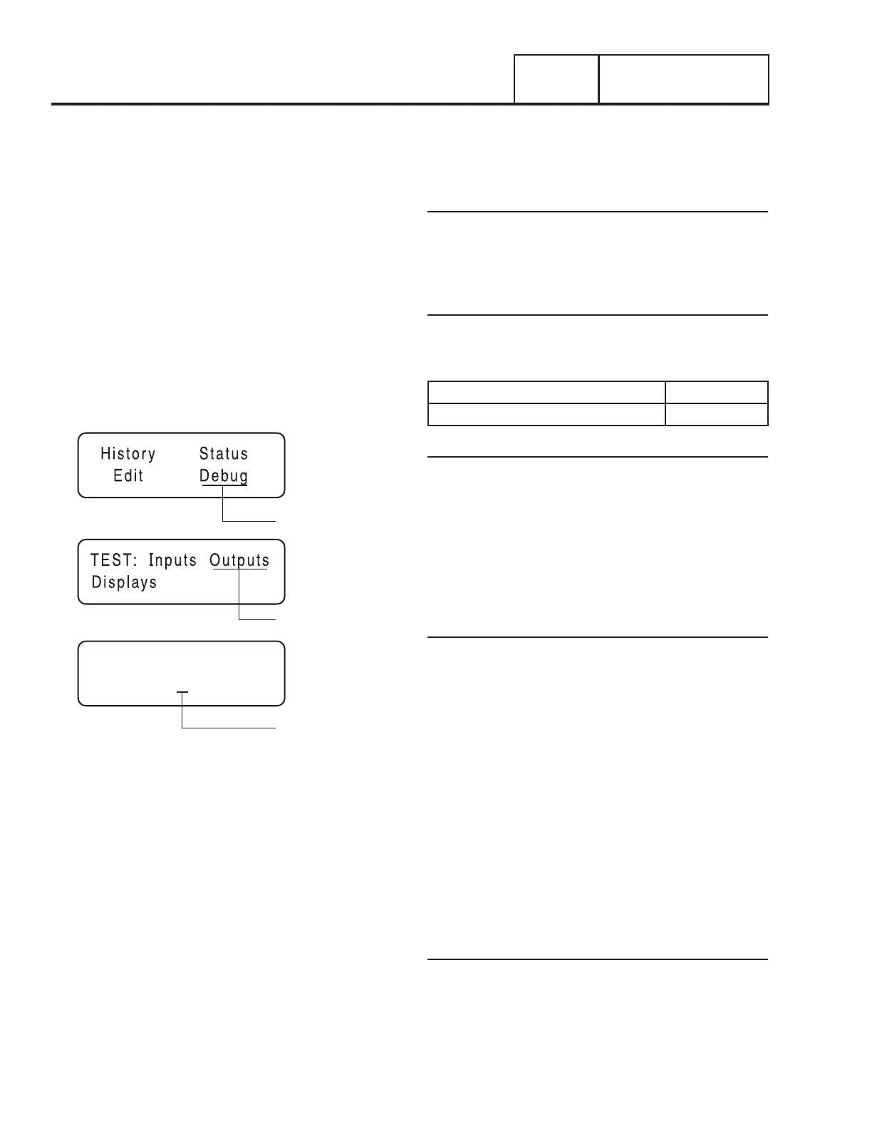
6. Navigate to the Digital Output display.
7. Press “ESC” until the display screen is present.
8. Press the right arrow key until “Debug” is flashing. Press
“Enter”.
9. Press the right arrow key until “Outputs” is flashing. Press
“Enter”.
DEBUG
OUTPUTS
OUTPUT 5
OUTPUTS 1 - 8:
1 0 1 1 0 0 0 1
Figure 127. The Home Page, Debug and Output Screens
10. Output 5 is Wire 14 out from the controller. If the controller
is functioning properly, Output 5 will change from a “0” to
a “1” while the unit is cranking.
a. If the VOM did NOT indicate voltage in Step 5 and
output did not change in Step 10, replace the controller.
b. If the VOM did NOT indicate voltage in Step 5 and the
output in Step 10 changed, proceed to Step 11.
11. Disconnect the 7.5 amp Fuse
12. Disconnect the J4 connector from the controller.
13. Set a VOM to measure resistance.
14. Connect one meter test lead to Wire 14 that was
disconnected in Step 3 and connect the other meter test
lead to Wire 14 at Pin 9 J4 (Wire 14). See Section 4.1
“Connector Pin Descriptions”.
a. If the VOM indicated CONTINUITY repeat Step 5 and
then retest.
b. If CONTINUITY is not measured, repair or replace Wire
14 between the J4 Connector and the fuel solenoid.
Results
Refer back to flow chart
TEST 52 – CHECK FUEL SOLENOID
Discussion
In Test 67, if battery voltage was delivered to Wire 14, the
fuel solenoid should have energized open. This test will verify
whether or not the fuel solenoid is operating.
Fuel Solenoid FS1 Nominal Resistance 27-33 ohms.
Fuel Solenoid FS2 Nominal Resistance 29 ohms.
Procedure: 8 and 12-20kW Units
1. Install a manometer to Port 2 on the fuel regulator. See
Figure 124 or Figure 126.
2. Set the AUTO-OFF-MANUAL Switch to MANUAL.
3. Proper gas pressure should be measured during cranking.
If gas pressure is measured, the fuel solenoid is operating.
If gas pressure is not measured, repair or replace the fuel
solenoid.
Procedure: 10kW Units
1. Remove the hose from fuel solenoid (FS2) and install a
manometer to Port 2 on the fuel regulator. See Figure 125.
2. Set the AUTO-OFF-MANUAL Switch to MANUAL.
3. Proper gas pressure should be measured during cranking.
If gas pressure is measured, both fuel solenoids are
operating. Discontinue testing.
4. If gas pressure was not measured in Step 3, remove fuel
solenoid FS2 and install a manometer to the bottom port
of the fuel regulator.
5. Set the AUTO-OFF-MANUAL Switch to MANUAL.
6. Proper gas pressure should be measured during cranking.
If gas pressure is measured, fuel solenoid FS1 is
operating. Replace fuel solenoid FS2. If gas pressure is
not measured, repair or replace fuel solenoid FS1.
Results
If fuel pressure was measured in any of the preceding tests it
indicates that the fuel solenoid is operating properly. Refer back
to the flow chart for the next test.

 Loading...


