PART 4
ENGINE/DC CONTROL
Page 100
Section 4.3
Operational Analysis
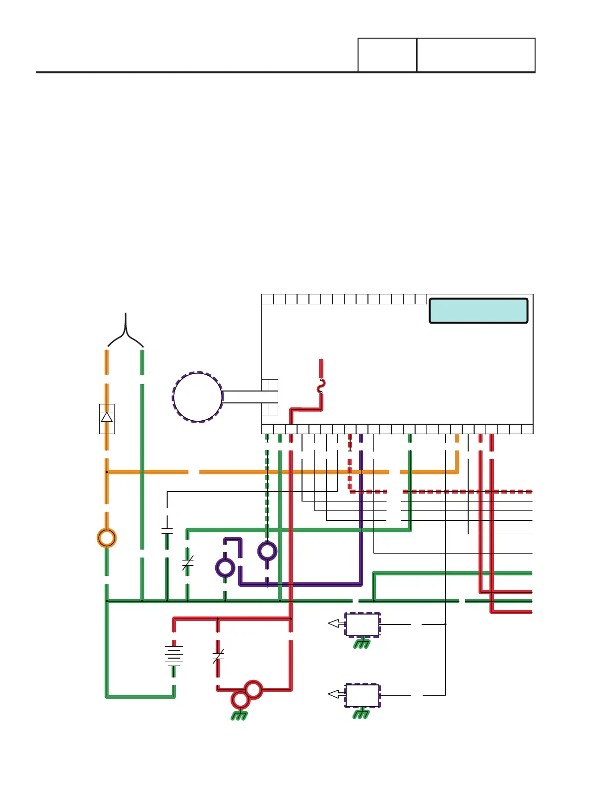
UTILITY VOLTAGE FAILURE AND ENGINE CRANKING
•After the controller’s 10-second timer has timed out, if Utility voltage is still below 65% of nominal, the controllers logic will
energize the internal crank relay followed by the internal run relay.
•When the internal crank relay energizes 12 VDC is delivered to the starter contactor relay (SCR) via Wire 56. When the SCR
energizes its contacts close and battery voltage is delivered to a starter contactor (SC). When the SC energizes its contacts close
and battery voltage is delivered to the starter motor (SM); the engine is now cranking.
•With the engine cranking a speed reference signal is generated by the magnetos and is delivered to the controller through Wire
18. If a valid signal is received, the controller will energize the internal run relay and deliver 12VDC on Wire 14. The fuel solenoid
energizes (opens) and fuel is available to the engine. The choke solenoid (CS) begins to operate and the controller grounds Wire
90, energizing the choke solenoid cyclically curing cranking, and continuously while running.
•During Cranking 3-5VDC is supplied to the rotor for field flash via a field boost diode connected in parallel with Wire 56.
•With ignition and fuel flow available the engine will start.
Crank Atempt # 1
F1
TO PCB
18
SP2
IM2
0
85
HTO
18
0
12V
BATTERY
SCR
IM1
SP1
56
0
820
817
818
819
ACTUATOR
J3
GOVERNOR
14
1886
0
FS
0
CS
J5
PRINTED CIRCUIT BOARD
CONTROLLER
J4
18171615141312109 1186 721 43 5 2322212019
90
0 13
817
818
819
85
820
14
14
14
210
LOP
0
86
56 194
209 23
141312109 1186 721 43 5
DIODE
FIELD BOOST
0
56
56
56
4
16
13
SCR
SM
SC
13 13
0
0
A
B
TO ROTOR
Figure 97.

 Loading...


