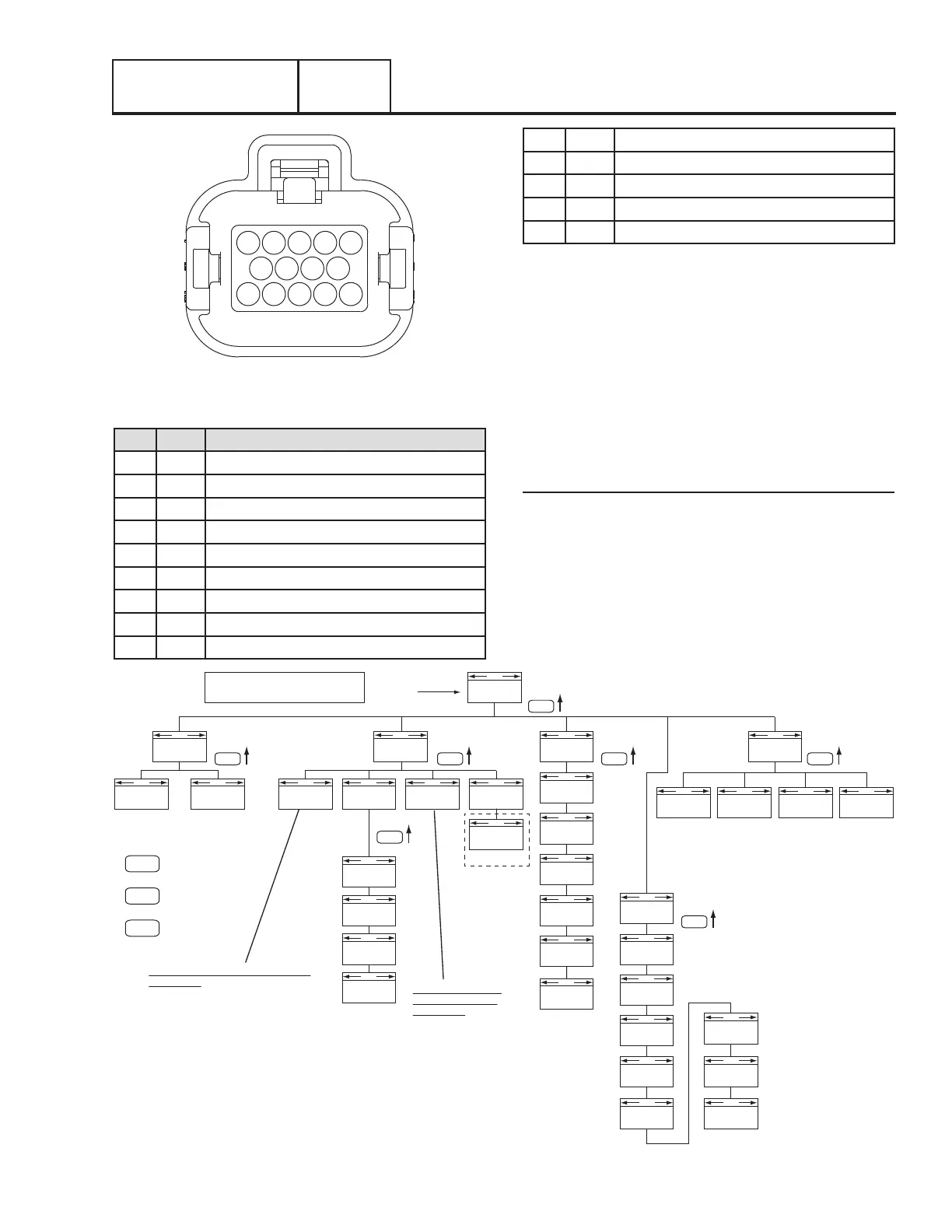
MAIN MENU
PASSWORD
“ESC, UP, UP ESC, DOWN, UP, ESC, UP, UP, ENTER”
RUN LOGALARM LOG
HISTORY STATUS
COMMANDSTATE VERSIONSDISPLAY
GENERATOR
FREQUENCY
ENGINE
HOURS
ENGINE
RPM
BATTERY
VO LTAGE
DEBUG
INPUTS OUTPUTS DISPLAYS
EDIT
RESET
MAINTENANCE
EXERCISE
TIME
CURRENT
TIME
ESC
Press the “ESCAPE” key
to jump back up through
the menu levels.
+ / -
Use the “+/-” key
to navigate through
the menu.
ENTER
Use the “ENTER” key
to select items or
enter data.
ESC
ESC
ESC
ESC
ESC
ESC
ESC
Password is entered
on this page.
FREQUENCY
LANGUAGE
START-UP
DELAY
QT TEST
If so equipped
The possible Status messages of the display
are as follows:
• Switched Off/Time & Date
• Ready to Run/Time & Date
• Utility Loss Delay/Pausing for X Seconds
• Cranking/Attempt # X
• Running in Exercise/Time & Date
• Running/Cooling Down
• Running - Warning/Warning Message
• Running - Alarm/Alarm Message
• Stopped - Alarm/Alarm Message
• Stopped - Warning/Warning Message
• Cranking/Pausing for X Seconds
• Running/Time & Date
• Running/Warming Up
• Cranking - Warning/Warning Message
• Cranking - Alarm/Alarm Message
The possible commands
on Line 2 of the display
are as follows:
• Switched Off
• Running Manually
• Stopped in Auto Mode
• Running - Utility Lost
• Running in Exercise
• Running from Radio
SOFTWARE
HARDWARE
IF APPLICABLE
NOTE: SOME VERSIONS MAY HAVE SLIGHTLY DIFFERENT PARAMETERS.
EDIT WITH
PASSWORD
REMOTE
START
RESET
MAINTENANCE
EXERCISE
TIME
CURRENT
TIME
FREQUENCY
LANGUAGE
START-UP
DELAY
CALIBRATE
VOLTS
Figure 90. Menu System Diagram
ENGINE/DC CONTROL
PART 4
Page 93
5
9 8 7 6
4 3 2 1
1014 13 12 11
Figure 89. J5 Connector (Harness Side)
Table 20. J5 High Voltage Connector Pin Descriptions
PIN WIRE CIRCUIT FUNCTION
1 N1 240 VAC Utility sensing voltage
2 T1 120VAC power for the battery charger
3 00 Neutral Connection for T1 (battery charger)
4
5 2 DPE Winding (AC Excitation power)
6 N2 240 VAC Utility sensing voltage
7
8
9
10 44 240 VAC Generator Voltage Sensing
11 11 240 VAC Generator Voltage Sensing
12 0 DC Field Excitation Ground
13 4 DC (+) Field Excitation
14 6 DPE Winding (AC Excitation power)
MENU SYSTEM NAVIGATION
To get to the MENU, use the “Esc” key from any page. It may
need to be pressed several times before getting to the menu
page. The currently selected menu is displayed as a flashing
word. Navigate to the desired menu item by using the +/- keys.
When the desired menu item is flashing, press the ENTER
key. Depending on the menu selected, there may be a list of
choices presented. Use the same navigation method to select
the desired screen (refer to the Menu System diagram, Figure
90). Refer to Section 1.10 “Nexus Control Panel Menu System
Navigation” for additional information.
Changing Settings (Edit Menu)
To change a setting, such as display contrast, go to the EDIT
menu and use the +/- keys to navigate to the setting to change.
Once this setting is displayed (e.g. Contrast), press the ENTER
key to go into the edit mode. Use the +/- keys to change the
setting, press the ENTER key to store the new setting.
Note: If the ENTER key is not pressed to save the new
setting, it will only be saved temporarily. The next time the
battery is disconnected, the setting will revert back to the
old setting.
Section 4.1
Description and Components

 Loading...


