TRANSFER SWITCH
PART 3
Page 65
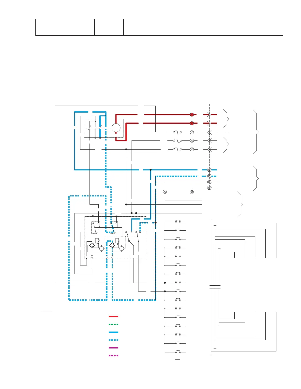
UTILITY SOURCE VOLTAGE FAILURE
If Utility source voltage should drop below 65% of nominal voltage for ten seconds, the controller will initiate engine start. After the
generator starts a five second engine warm-up timer is initiated. During this warm-up the generator is running at rated frequency
and voltage. Figure 67 is a schematic representation of the transfer switch with the Generator running with voltage available to the
transfer switch.
Generator voltage is available on CONTACTOR terminals E1 and E2.
•The controller’s logic is holding Wire 23 open from ground.
•Generator voltage from terminal E2 is available at the standby coil (C2); generator voltage from Terminal E1 is available to the
transfer relay at Pin 9. The transfer relay is not energized so E1 voltage will not go through the N.O. contact (9 & 6) to Wire 205.
Section 3.2
Operational Analysis
SW3
SW2
E2
CIRCUIT 13
VR2
(16 CIRCUIT SHOWN FOR REFERENCE ONLY)
TR1-TRANSFER RELAY
SW2, SW3-LIMIT SWITCHES
TB1-TERMINAL STRIP
SW1-AUTOMATIC TRANSFER SWITCH
N-NEUTRAL
F1, F2, F3-5A, 600V FUSE
C1-UTILITY COIL & RECTIFIER
C2-GENERATOR COIL & RECTIFIER
LC-CIRCUIT BREAKER (LOADS)
LEGEND
B
N2A
B
T1A
N2A
B E2
SW1
A
COM
C1
VR1
COM
CIRCUIT 15
CIRCUIT 16
E2
T2
CIRCUIT 12
CIRCUIT 8
CIRCUIT 11
CIRCUIT 7
CIRCUIT 3
CIRCUIT 4
T1
T1A
C2
T1
T2
CIRCUIT 2
CIRCUIT 1
CIRCUIT 5
CIRCUIT 9
CIRCUIT 6
CIRCUIT 10
14 CIRCUIT LOAD CENTER
12 CIRCUIT LOAD CENTER
10 CIRCUIT LOAD CENTER
8 CIRCUIT LOAD CENTER
16 CIRCUIT LOAD CENTER
NO
N2A
A
B
126
NO NCNC
205
B
B
E1
N1A
126
N1A
77
1 4
205
23
99
3 6
TR1
N1A
E1
CONTROL
BLACK (MAIN 1)
RED (MAIN 2)
NEUTRAL (WHITE)
GROUND (GREEN)
E1
N1A
E2
N2A
E1
E2
CIRCUIT 14
CONNECTION
NEUTRAL
SWITCH
INSIDE
E2
T1A
N2A
N1A
E1
N2A
N1A
23
F1
E1
N1
F2
F3
T1
N2
23
240VAC TO
PANEL
MAIN DISTRIBUTION
NEUTRAL (WHITE)
GROUND (GREEN)
RED
GENERATOR
TO
OUTPUT
UTILITY
OUTPUT
BLACK
N1
T1
N2
23
240VAC
SENSING
TRANSFER
GENERATOR
PANEL
CONTROL
TS TO
EXTERNAL CONNECTION BOX
194
T1A
194
194
120VAC
OUTPUT
LOAD SENSING
N1 UTILITY VOLTAGE
E1 GENERATOR VOLTAGE
DC
N2 UTILITY VOLTAGE
(PCB) GROUND CONTROL
E2 GENERATOR VOLTAGE
Figure 67. Utility Source Voltage Failure

 Loading...


