PART 4
ENGINE/DC CONTROL
Page 138
Section 4.5
Diagnostic Tests
test lead to the ground terminal, measure and record the
resistance.
Results
1. If the VOM indicated 16 ohms of resistance in Step 3, a
short to ground exists on Wire 14 between the FS and the
J4 connector. Repair and replace as needed.
2. If the VOM indicated CONTINUITY in Step 3, replace the FS
Procedure: 10kW
1. Set a Volt-Ohm-Milliammeter (VOM) to measure
resistance.
2. Disconnect Wire 14 from the fuel solenoid (FS), fuel
solenoid 2 (FS2), and the choke solenoid (CS).
3. Connect one meter test lead to the FS terminal from
which Wire 14 was removed. Connect the other meter
test lead to the ground terminal, measure and record the
resistance.
4. Connect one meter test lead to the FS2 terminal from
which Wire 14 was removed. Connect the other meter
test lead to the ground terminal, measure and record the
resistance.
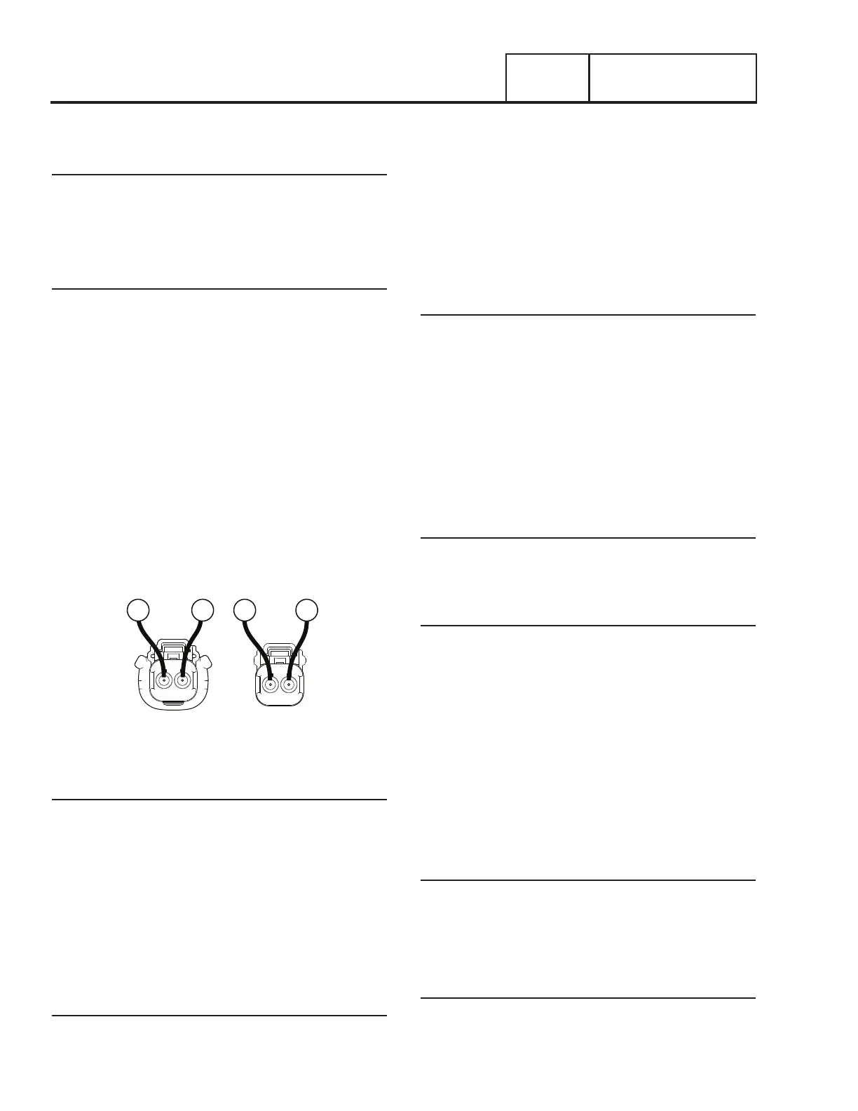
5. Refer to Figure 156 in reference to the CS connector.
Connect one meter test lead to Pin 1 and the other meter
test lead to Pin 2, measure and record the resistance.
FEMALE SIDE
MALE SIDE
2 1
1 2
90
9014
14
Figure 156. C3 Choke Solenoid Connector
Results
1. If the VOM indicated CONTINUITY in Step 3, replace the
FS solenoid.
2. If the VOM indicated CONTINUITY in Step 4, replace the
FS2 solenoid
3. If the VOM indicated CONTINUITY in Step 5, replace the
CS solenoid.
4. Refer to Table 24 and if the VOM indicated the correct
resistance for the component, a short to ground exists on
Wire 14. Repair or replace Wire 14 as needed.
Procedure: 12kW-20kW
1. Set a Volt-Ohm-Milliammeter (VOM) to measure
resistance.
2. Disconnect Wire 14 from the fuel solenoid (FS) and the
choke solenoid (CS).
3. Connect one meter test lead to the FS terminal from
which Wire 14 was removed. Connect the other meter
test lead to the ground terminal, measure and record the
resistance.
4. Refer to Figure 156 in reference to the CS connector.
Connect one meter test lead to Pin 1 and the other meter
test lead to Pin 2, measure and record the resistance.
Results
1. If the VOM indicated CONTINUITY in Step 3, replace the
FS solenoid.
2. If the VOM indicated CONTINUITY in Step 4, replace the
CS solenoid.
3. Refer to Table 24 and if the VOM indicated the correct
resistance for the component, a short to ground exists on
Wire 14. Repair and replace Wire 14 as needed.
TEST 68 – TEST CRANK CIRCUIT
Discussion
Wire 56 provides 12 VDC during cranking only. If the VOM
indicated CONTINUITY in the previous test, one of the possible
causes could be a faulty relay or solenoid.
Procedure: 8kW
1. Set a Volt-Ohm-Milliammeter (VOM) to measure
resistance.
2. Disconnect Wire 56 from the starter contactor (SC) and
disconnect the choke solenoid (CS)
3. Connect one meter test lead to the SC terminal from
which Wire 56 was removed. Connect the other meter
test lead to the ground terminal, measure and record the
resistance.
4. Refer to Figure 157 in reference to the CS connector.
Connect one meter test lead to Pin 1 and the other meter
test lead to Pin 2, measure and record the resistance.
Results
1. If the VOM indicated 4 ohms of resistance in Step 3, a
short to ground exists on Wire 56 between the SC and the
J4 connector. Repair or replace as needed.
2. If the VOM indicated CONTINUITY in Step 3, replace the SC
Procedure: 10kW-20kW
1. Set a Volt-Ohm-Milliammeter (VOM) to measure
resistance.

 Loading...


