ENGINE/DC CONTROL
PART 4
Page 91
connection through a fuse (F3) in the transfer switch. This 120
VAC source must be connected to the Generator in order to
operate the charger.
During a Utility failure, the charger will momentarily be turned
off until the Generator is connected to the Load. During normal
operation, the battery charger supplies all the power to the
Nexus controller; the Generator battery is not used to supply
power.
The battery charger will begin its charge cycle when battery
voltage drops below approximately 12.6V. The charger provides
current directly to the battery dependant on temperature, and
the battery is charged at the appropriate voltage level for 18
hours. At the end of the 18 hour charge period battery charge
current is measured when the Generator is off. If battery charge
current at the end of the 18 hour charge time is greater than
a pre-set level, or the battery open-circuit voltage is less than
approximately 12.5V, an “Inspect Battery” warning is raised. If
the engine cranks during the 18 hour charge period, then the 18
hour charge timer is restarted.
At the end of the 18 hour charge period the charger does one of
two things. If the temperature is less than approximately 40ºF
the battery is continuously charged at a voltage of 14.1V (i.e.
the charge voltage is changed from 14.6V to 14.1V after 18
hours). If the temperature is above approximately 40ºF then the
charger will stop charging the battery after 18 hours.
The battery has a similar role as that found in an automobile
application. It sits doing nothing until it either self-discharges
below 12.6V or an engine crank occurs (i.e. such as occurs
during the weekly exercise cycle). If either condition occurs the
battery charge will begin its 18 hour charge cycle.
AUTO-OFF-MANUAL
This 3-position switch permits the operator to (a) select fully
automatic operation, (b) start the Generator manually, or (c)
stop the engine and prevent the automatic startup. See Figure
84 for the location of the switch.
Escape
MAIN FUSE
AUTO OFF MANUAL
7.5 AMP
Enter
Figure 84. Auto-Off-Manual Switch
7.5 AMP FUSE
The fuse protects the controller against excessive current. If
the fuse has blown, engine cranking and operation will not be
possible. Should fuse replacement become necessary, use
only an equivalent 7.5 amp replacement fuse.
Figure 85. Typical 7.5 Amp Fuse
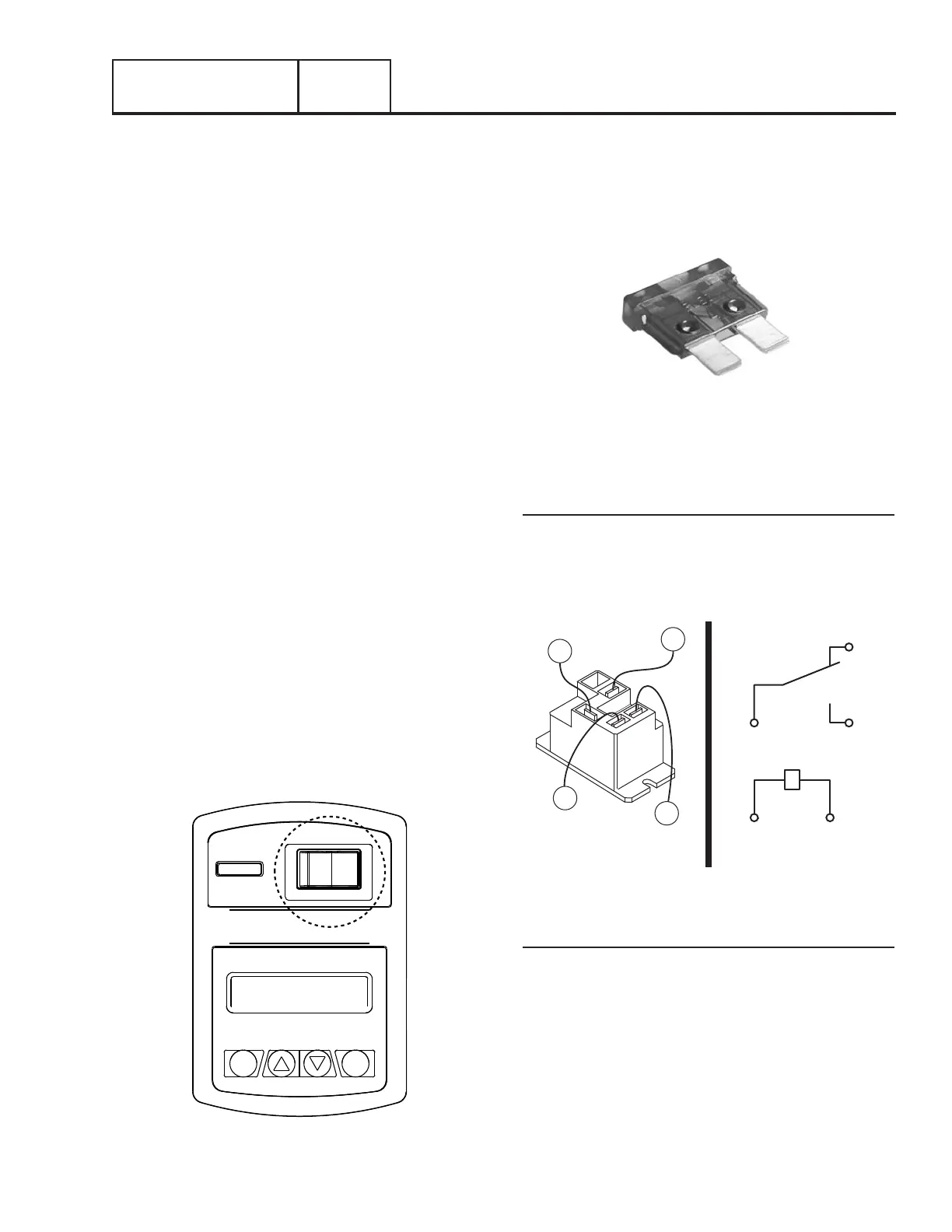
STARTER CONTACTOR RELAY/SOLENOID
V-Twin Models
The starter contactor relay (SCR) provides a safe and controlled
method of energizing the solenoid located on the starter. The
controller is responsible for energizing the relay when the start
command is given. Refer to Figure 86.
COM NO
16
13
56 0
13
16
0
56
Figure 86. Starter Contactor Relay
(
V-twin
Units)
Single Cylinder Models
The Starter Contactor (SC) is located in the engine compartment
and is mounted against the firewall. The SC provides the
electrical connection to safely engage the starter. See Figure
87.
Section 4.1
Description and Components

 Loading...


