TRANSFER SWITCH
PART 3
Page 77
Results
1. If normal transfer to the “Standby” position occurs,
discontinue testing.
2. If transfer to the “Standby” position did NOT occur but the
Generator continued to run for longer than 10 seconds,
and the VOM did not indicate voltage across E1 and E2,
proceed to Test 1 “Check AC output voltage” and Test 2
“Check Main Line Circuit Breaker.”
3. If transfer to the “Standby” position did NOT occur and
the VOM indicated voltage across E1 and E2 this test is
GOOD; refer to back to flow chart.
4. If transfer to the “Standby” position did NOT occur and
Generator faulted on under-voltage, refer to Problem 1
“Generator Shuts Down for Under-voltage.”
TEST 21 – CHECK MANUAL TRANSFER
SWITCH OPERATION
Discussion
In automatic operating mode, when Utility source voltage drops
below a preset level, the engine should crank and start. On
engine startup, an “engine warm-up timer” on the Generator
should start timing. After the timer has expired (about
15 seconds), the transfer relay (TR1) energizes to deliver
generator source voltage to the standby closing coil terminals.
If generator voltage is available to the standby closing coil
terminals, but transfer to Standby does not occur, the cause
of the failure may be (a) a failed standby closing coil and/or
bridge rectifier, or (b) a seized or sticking actuating coil or load
contact. This test will help you evaluate whether any sticking
or binding is present in the CONTACTOR
Procedure
1. Set the generator main line circuit breaker (MLCB) to the
“Open” position.
2. Set the AUTO-OFF-MANUAL switch to the OFF position.
3. Disconnect Utility from the transfer switch.
Do not attempt manual transfer switch operation until all
voltage to the switch have been disconnected. Failure
to turn off all power voltage supplies may result in
extremely hazardous and possibly lethal electrical shock.
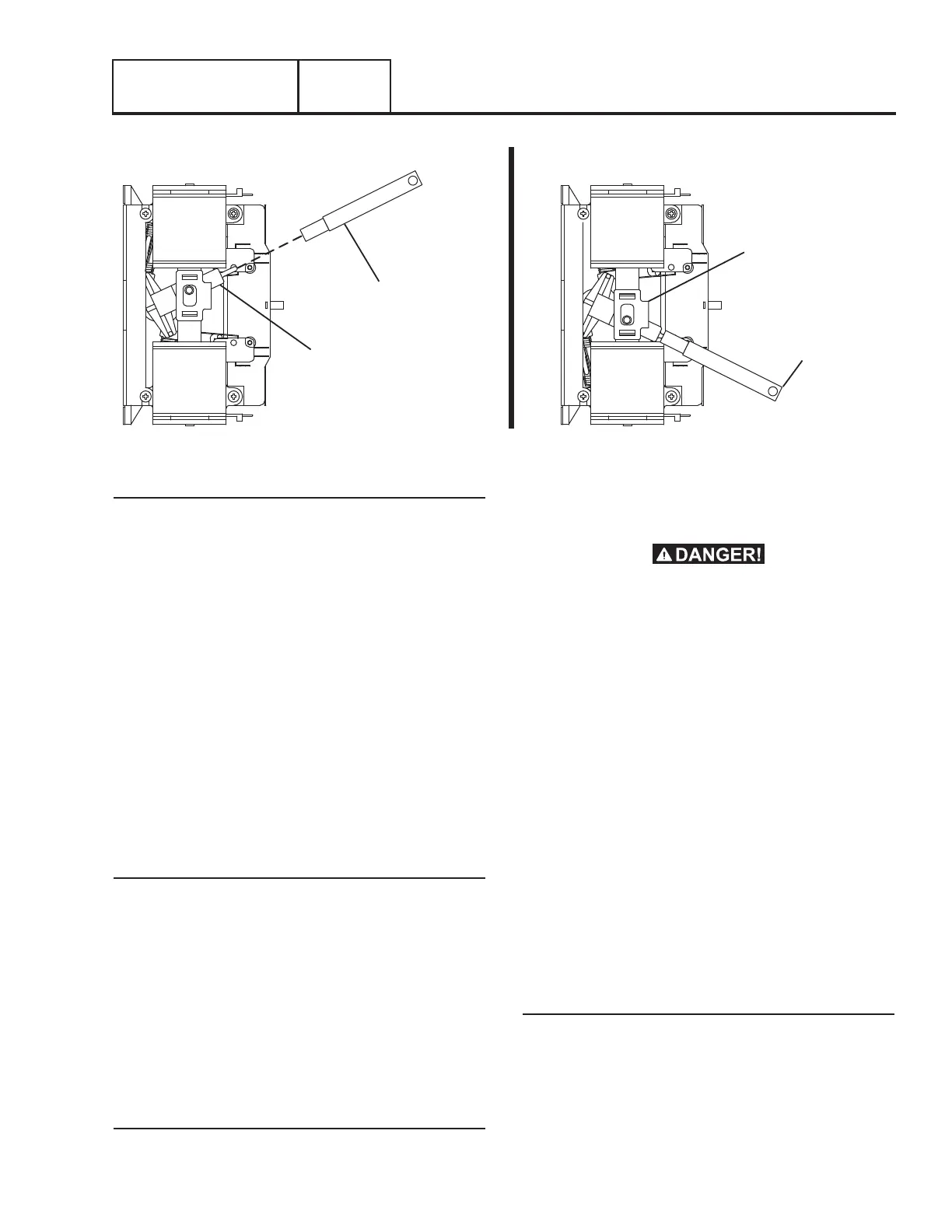
4. Locate the manual transfer handle inside the switch
enclosure.
5. Insert the un-insulated end of the handle over the transfer
switch-operating lever. Refer to Figure 74.
a. Manual actuate the CONTACTOR lever to the “Utility”
position.
b. Actuate the operating lever down to the “Standby”
position.
6. Repeat Step 5 several times. When the CONTACTOR
lever is moved slight force should be needed until the
lever reaches its center position. As the lever moves past
its “over center” position, an over-center spring should
snap the movable LOAD contacts against the stationary
STANDBY or UTILITY contacts.
7. Actuate the CONTACTOR to the “Utility” position.
Results
1. If there is no evidence of binding, sticking, or excessive
force required the test is GOOD; refer back to the flow
chart.
2. If evidence of sticking, binding, excessive force is required
to move the CONTACTOR, find cause of binding or sticking
and repair or replace damaged components.
Section 3.4
Diagnostic Tests
Figure 74. Manual Transfer Switch Operation
MANUAL
TRANSFER
HANDLE
TRANSFER
SWITCH
OPERATING
LEVER
MANUAL
TRANSFER
HANDLE
TRANSFER
SWITCH
OPERATING
LEVER
LOAD CONNECTED TO
UTILITY POWER SOURCE
LOAD CONNECTED TO
STANDBY POWER SOURCE

 Loading...


