Page 4
Specifications
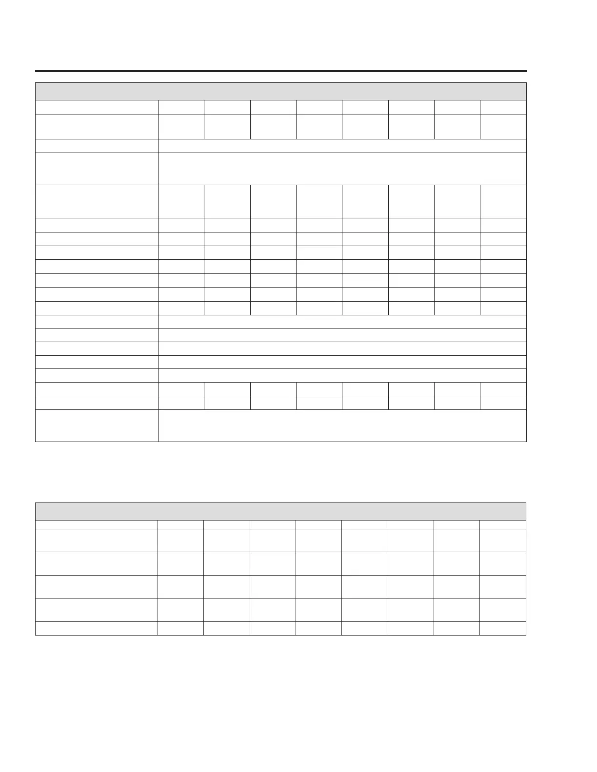
GENERATOR
Unit
8 kW 10 kW 13 kW 14 kW 15 kW 16 kW 17 kW 20 kW
Rated Max. Continuous Power Capacity
(Watts*)
7,000 NG
8,000 LP
9,000 NG
10,000 LP
13,000 NG
13,000 LP
13,000 NG
14,000 LP
15,000 NG
15,000 LP
16,000 NG
16,000 LP
16,000 NG
17,000 LP
18,000 NG
20,000 LP
Rated Voltage 240
Rated Voltage at No-Load (NG)
Older controller P/N 0H6680A
Newer controller P/N 0H6680B
250-254
240-244
Rated Max. Continuous Load Current
(Amps)
240 Volts (LP/NG) 33.3/29.2 41.6/37.5 54.2/54.2 58.3/54.2 62.5/62.5 66.6/66.6 70.8/66.6 83.3/75.0
Main Line Circuit Breaker
35 Amp 45 Amp 55 Amp 60 Amp 65 Amp 65 Amp 65 Amp 100 Amp
Circuits*** 50A, 240V - - 1 - 1 1 1 -
40A, 240V - 1 1 1 1 1 1 -
30A, 240V 1 1 - - - - - -
20A, 240V 1 - 1 1 1 1 1 -
20A, 120V 3 3 4 6 5 5 5 -
15A, 120V 3 5 4 4 5 5 5 -
Phase 1
Number of Rotor Poles 2
Rated AC Frequency 60 Hz
Power Factor 1
Battery Requirement Group 26R, 12 Volts and 525 CCA Minimum
Weight (unit only in lbs.)
340 387/353 439 439 455/421 439 455/421 450
Enclosure Steel Steel/Aluminum Steel Steel
Steel/Aluminum Steel Steel/Aluminum Aluminum
Normal Operating Range This unit is tested in accordance to UL 2200 standards with an operating temperature of 20° F (-29° C) to 122°F. (50° C). For
areas where temperatures fall below 32° F (0° C), a cold weather kit is highly recommended. When operated above 77° F (25° C)
there may be a decrease in engine power. (Please reference the engine specifications section).
* Maximum wattage and current are subject to and limited by such factors as fuel Btu content, ambient temperature, altitude, engine power and condition, etc.
Maximum power decreases about 3.5 percent for each 1,000 feet above sea level; and also will decrease about 1 percent for each 6 C (10 F) above 16 C (60 F)
ambient temperature.
** Load current values shown for 120 volts are maximum TOTAL values for two separate circuits. The maximum current in each circuit must not exceed the value
stated for the 240 volts.
*** Circuits to be moved must be protected by same size breaker. For example, a 15 amp circuit in the main panel must be a 15 amp circuit in the transfer switch.
STATOR WINDING RESISTANCE VALUES / ROTOR RESISTANCE*
8 kW 10 kW 13 kW 14 kW 15 kW 16 kW 17 kW 20 kW
Power Winding: Across 11 & 22 0.1660-
0.1930
0.1895-
0.2203
0.1003-
0.1165
0.1003-
0.1165
0.0746-
0.0866
0.0746-
0.0866
0.0746-
0.0866
0.0415-
0.0483
Power Winding: Across 33 & 44 0.1660-
0.1930
0.1895-
0.2203
0.1003-
0.1166
0.1003-
0.1166
0.0746-
0.0866
0.0746-
0.0866
0.0746-
0.0866
0.0415-
0.0483
Sensing Winding: Across 11 & 44 0.378-.4392 0.425-0.4938 0.2484-
0.2887
0.2484-
0.2888
0.197-0.229 0.197-0.229 0.197-0.229 0.137-0.1594
Excitation Winding: Across 2 & 6 1.0318-
0.1930
1.0935-
1.2708
0.876-1.017 0.876-1.018 0.780-0.906 0.780-0.906 0.780-0.906 0.7318-
0.8504
Rotor Resistance 6.30-7.32 6.30-7.32 7.58-8.80 7.58-8.81 8.37-9.72 8.37-9.72 8.37-9.72 9.54-11.10
* Resistance values shown are based on new windings at 20° C. Actual readings may vary based on type of meter used and any other components or
connections included in the circuit being tested.

 Loading...


