PART 2
AC GENERATORS
Page 42
Section 2.2
Operational Analysis
ROTOR RESIDUAL MAGNETISM
The Generators revolving field (rotor) provides the magnetic
flux required to induce voltage into the stator and excitation
windings (DPE). Some “residual” magnetism is always present
in the rotor. Although residual magnetism is present it is only
sufficient to induce a very low AC output, typically 0 to 6 VAC,
and not enough to make the excitation winding (DPE) produce
enough voltage for the AVR to operate. In order to make the
DPE winding produce enough voltage to turn on and allow the
AVR to operate, a Field Boost (flash) circuit is used during
cranking.
FIELD BOOST
During the engines crank cycle, the control panel provides
battery voltage (12 VDC) on Wire 56 to energize the starter
contactor relay (SCR). Wire 56 also connects to Wire 4
(positive field voltage) through a field boost diode.
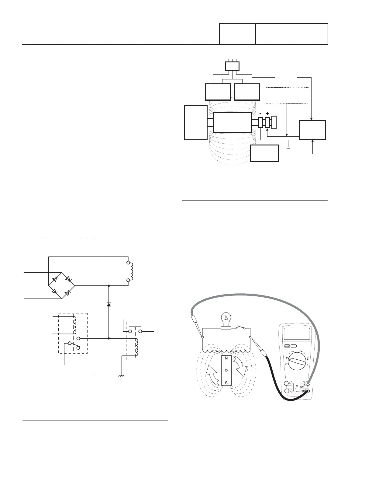
The field boost system is shown schematically in Figure 42.
When the controller cranks the engine, battery voltage is
applied through Wire 56 and the boost diode to Wire 4. This
provides the current necessary to energize the field winding.
The diode PREVENTS excitation voltage from feeding into wire
56 while the unit is running during normal operation.
Note: Field boost voltage is available only while the crank
relay is energized (i.e. during the engines crank cycle).
J5-12
J5-13
FIELD BOOST DIODE
STARTER
CONTACTOR
TO
STARTER
+12 VDC
+12 VDC
BRIDGE
RECTIFIER
CRANK RELAY
CONTROLLER
ROTOR
13
Figure 42. Field Boost Circuit
OPERATION
Engine Cranking
When the engine is cranking, field boost voltage causes the rotor
to magnetize. The rotor magnetic field induces a voltage into
the stator AC power windings, and the stator excitation (DPE)
windings. During cranking, field boost magnetism is capable of
creating approximately one-half the unit’s rated voltage.
STATOR
EXCITATION
WINDING
VOLTAGE
REGULATOR
FIELD BOOST FROM
CRANK CIRCUIT
STATOR
POWER
WINDING
STATOR
POWER
WINDING
MAGNETIC
FIELD
MAGNETIC
FIELD
MLB = MAIN LINE CIRCUIT BREAKER
ROTOR
SENSING
TO LOAD
MLB
ENGINE -
DIRECT
DRIVE
Figure 43. Operating Diagram
Field Excitation
The AC voltage from the DPE winding provides power to the
AVR. The AVR rectifies and regulates the AC voltage to DC
voltage, and provides the DC voltage to the rotor through Wires
4 and 0. When the starter disengages (cranking stopped), the
AVR continues to provide excitation voltage to the rotor.
The AVR senses the AC output voltage through Sensing Wires
11 and 44, which are connected to the main power leads (11
and 44) in the stator can. The AVR will continue to increase
excitation voltage to the rotor until the desired AC output voltage
is reached. It will continue to “regulate” excitation voltage as
necessary to provide a constant AC output voltage to the load.
STATOR
ROTOR
MAGNETIC FIELD
100 VAC
Figure 44. Low Excitation voltage = Low Magnetic lines of
Flux = Low AC Output.

 Loading...


