PART 4
ENGINE/DC CONTROL
Page 120
Section 4.5
Diagnostic Tests
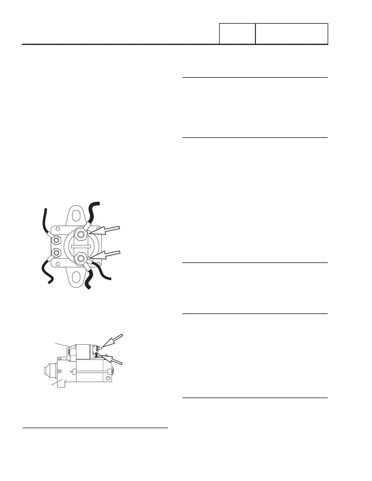
Refer to Figure 114 and 115 for Test Points
1. Set Volt-Ohm-Milliammeter (VOM) to measure DC voltage.
2. Connect the positive meter test lead to the positive post
of the battery and connect the negative meter test lead to
the negative post of the battery. The VOM should indicate
battery voltage. This measure will be a reference during
the testing procedure.
3. Connect the positive meter test lead to Test Point 1 and
connect the negative meter test lead to a clean frame
ground, measure and record the voltage.
4. Connect the positive meter test lead to Test Point 2 and
connect the negative meter test lead to a clean frame
ground.
5. Set the AUTO-OFF-MANUAL switch to the MANUAL
position; measure and record the voltage at Test Point 2
(Wire 16). The contactor should energize.
16
TO STARTER
13
TO BATTERY
13
TO CONTROLLER
CONNECTOR J4 - PIN 3
0
TO GROUND
56
TO CONTROLLER
TEST POINT 2
TEST POINT 1
Figure 114. The Starter Contactor (Single Cylinder Units)
STARTER
CONTACTOR
STARTER
MOTOR
TEST POINT 2
TEST POINT 1
Figure 115. The Starter Contactor (V-twin Units)
Results
1. If battery voltage was indicated in Steps 3 and 4, refer
back to the flow chart.
2. If battery voltage was indicated in Step 3, but not in Step
4, replace the starter contactor.
V-Twin Only
3. If the VOM did not indicate battery voltage in Step 4 (on
Wire 16), repair or replace Wire 16 between the SCR and
the contactor.
TEST 49 – TEST STARTER MOTOR
Conditions Affecting Starter Motor Performance
1. A binding or seizing condition in the starter motor bearings.
2. A shorted, open or grounded armature.
a. Shorted armature (wire insulation worn and wires
touching one another). Will be indicated by low or no
RPM.
b. Open armature (wire broken) will be indicated by low or
no RPM and excessive current draw.
c. Grounded armature (wire insulation worn and wire
touching armature lamination or shaft). Will be indicated
by excessive current draw or no RPM.
3. A defective starter motor switch.
4. Broken, damaged or weak magnets.
5. Starter drive dirty or binding.
Discussion
Test 46 verified that the circuit board is delivering DC voltage to
the starter contactor relay (SCR). Test 47 verified the operation
of the SCR. Test 48 verified the operation of the starter
contactor (SC). Another possible cause of an “engine won’t
crank” problem is a failure of the starter motor.
Procedure
The battery should have been checked prior to this test and
should be fully charged.
Set a VOM to measure DC voltage (12 VDC). Connect the meter
positive (+) test lead to the starter contactor stud which has
the small jumper wire connected to the starter. Connect the
common (-) test lead to the starter motor frame.
Set the AUTO-OFF MANUAL Switch to its “MANUAL” position
and observe the meter. Meter should indicate battery voltage,
starter motor should operate and engine should crank.
Results
1. If battery voltage is indicated on the meter but starter
motor did NOT operate, remove and bench test the starter
motor (see following test).
2. If battery voltage was indicated and the starter motor tried
to engage (pinion engaged), but engine did NOT crank,
check for mechanical binding of the engine or rotor.

 Loading...


