PART 6
DISASSEMBLY
Page 160
Section 6.1
Major Disassembly
19. Remove Engine: Using proper lifting equipment remove
the engine. See Figure 206.
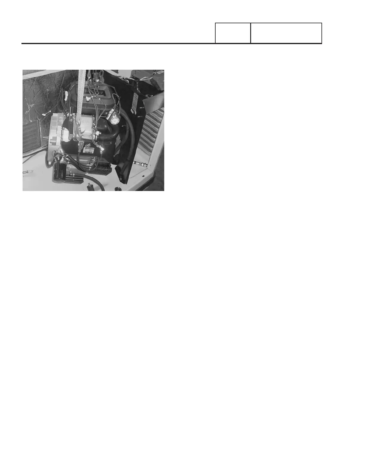
Figure 205.
TORQUE REQUIREMENTS
(UNLESS OTHERWISE SPECIFIED)
STATOR BOLTS ................................................ 6 ft-lbs ( +1 / -0 )
ROTOR BOLT ................................................................ 30 ft-lbs
ENGINE ADAPTOR ....................................................... 25 ft-lbs
EXHAUST MANIFOLD .................................................. 18 ft-lbs
M5-0.8 TAPTITE SCREW INTO ALUMINUM .......... 25-50 in-lbs
M5-0.8 TAPTITE SCREW INTO PIERCED HOLE ... 25-50 in-lbs
M6-1.0 TAPTITE SCREW INTO ALUMINUM .......... 50-96 in-lbs
M6-1.0 TAPTITE SCREW INTO PIERCED HOLE ... 50-96 in-lbs
M6-1.0 TAPTITE SCREW INTO WELDNUT
............ 50-96 in-lbs
M8-1.25 TAPTITE SCREW INTO ALUMINUM ......... 12-18 ft-lbs
M8-1.25 TAPTITE SCREW INTO PIERCED HOLE ... 12-18 ft-lbs
M6-1.0 NYLOK NUT ONTO WELD STUD .............. 16-65 in-lbs
M6-1.0 NYLOK NUT ONTO HINGE STUD ............. 30-36 in-lbs
Note: torques are dynamic values with ±10% tolerance
unless otherwise noted.

 Loading...


