ENGINE/DC CONTROL
PART 4
Section 4.5
Diagnostic Tests
3. Press the right arrow key until “Debug” begins to flash.
4. Press “Enter.”
5. Press the right arrow key until “QT Test” beings to flash.
6. Press “Enter.”
7. The generator should start and run its normal exercise
period.
Results
1. In all models, if the unit starts in MANUAL, but fails
to exercise without any ALARMS present, replace the
controller.
TEST 66 – TEST CRANKING AND RUNNING
CIRCUITS
Discussion
This test will check all of the circuits that are “Hot” with battery
voltage and which could cause the Main Fuse to blow. Refer
to Table 24 throughout the procedure for the known resistance
values of components.
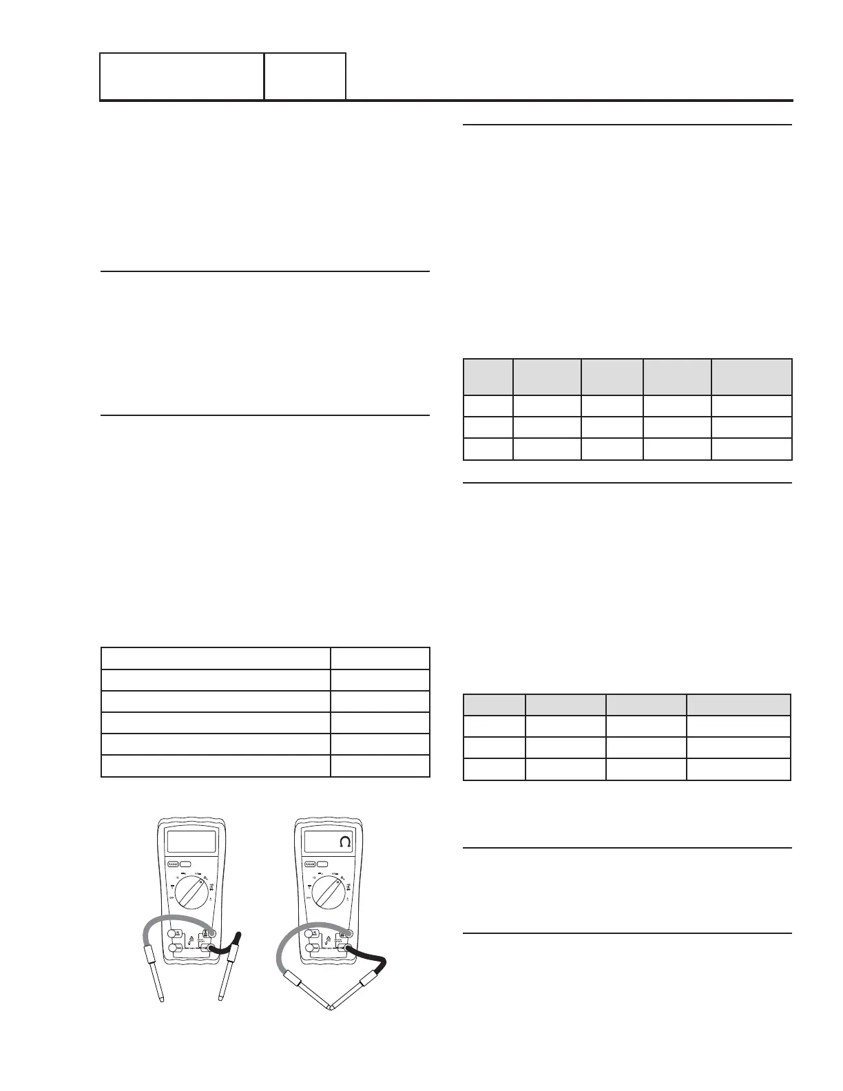
Figure 155 shows the Volt-Ohm-Milliammeter (VOM) in two
different states. The left VOM indicates an OPEN circuit or
INFINITY. The right VOM indicates a dead short or CONTINUITY.
Throughout the troubleshooting, refer back to Figure 155 as
needed to understand what the meter is indicating about the
particular circuit that was tested.
Note: CONTINUITY is equal to .01 ohms of resistance or a
dead short.
Table 24. Components Resistance Values
Starter Contactor 8Ω
Starter Contactor Relay 155Ω
Main Fuel Solenoid 16Ω
10kW Fuel Solenoid 2 7Ω
Transfer Relay 90Ω
Choke Solenoid 4Ω
OL
OPEN LINE “INFINITY”
SHORT "CONTINUITY"
.01
Figure 155.
Procedure
1. Set a Volt-Ohm-Milliammeter (VOM) to measure
resistance.
2. Disconnect the J4 connector from the controller.
3. Connect one meter lead to a clean frame ground and
connect the other meter test lead to each of the following
tests points in Table 25, measure and record the
resistance.
Table 26 has been provided to record the results of this test.
Additional copies of this table can be found in Appendix A
“Supplemental Worksheets” at the back of this manual.
Table 25. Resistance Measurements
Test
Point
Pin
Location
Circuit 8kW 10kW-
20kW
1 J4 Pin 9 Wire 14 16Ω 16Ω
2 J4 Pin 17 Wire 56 4Ω 155Ω
3 J4 Pin 19 Wire 194 OPEN OPEN
Results
1. Compare the results of Step 3 with Table 25 according to
the different kW range.
a. If the VOM indicated CONTINUITY at Test Point 1
proceed to Test 67
b. If the VOM indicated CONTINUITY at Test Point 2
proceed to Test 68
c. If the VOM indicated CONTINUITY at Test Point 3
proceed to Test 69
d. If the VOM indicated proper resistance values at all Test
Points, replace the controller
Table 26. Test 66 Results
Test Point Pin Location Circuit Result
1 J4 Pin 9 Wire 14
2 J4 Pin 17 Wire 56
3 J4 Pin 19 Wire 194
TEST 67 – TEST RUN CIRCUIT
Discussion
Wire 14 provides 12 VDC during cranking and running. If the
VOM indicated CONTINUITY in the previous test, one of the
possible causes could be a faulty relay or solenoid.
Procedure: 8kW
1. Set a Volt-Ohm-Milliammeter (VOM) to measure
resistance.
2. Disconnect Wire 14 from the fuel solenoid (FS)
3. Connect one meter test lead to the FS terminal from
which Wire 14 was removed. Connect the other meter
Page 137

 Loading...


